


6809471A67-O
August 20, 2003
27
Level 1 and 2 Service Manual
Disassembly
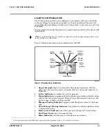
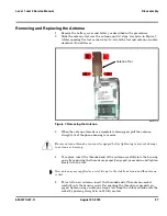
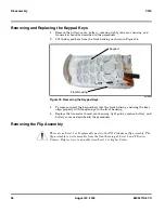
Removing and Replacing the Antenna
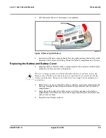
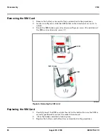
1.
Remove the battery cover and battery as described in the procedures.
2.
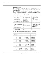
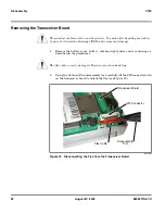
Slide the antenna tool over the antenna until it stops. As shown in Figure 7,
while squeezing the tool as shown by (A), rotate the tool and antenna counter-
clockwise (B) until loose.
3.
When the antenna threads are completely disengaged, pull the antenna
straight out of the phone housing to remove.
4.
To replace, insert the threaded end of the antenna carefully into the housing
and, after ensuring the threads are properly engaged, press down and tighten
firmly with the tool.
5.
To install a new antenna, insert the threaded end of the antenna socket
carefully into the housing and, after ensuring the threads are properly en-
gaged, tighten using an antenna torque tool. Snap the stubby antenna into the
socket by pushing straight in until fully seated.
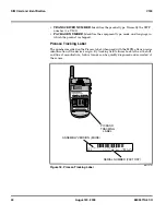
001073-O
Figure 7. Removing the Antenna
G
Ensure antenna threads are properly engaged before tightening to prevent damage
to antenna or housing.
➧
New antennas are supplied as a set of two parts: the stubby antenna and the antenna
socket.
A
B
A
Antenna Tool
Содержание V150
Страница 1: ...Level 1 and 2 Service Manual V150 Dual Band Wireless Telephone GSM 900 DCS 1800MHz with GPRS ...
Страница 2: ......
Страница 4: ...4 August 20 2003 V150 ...
Страница 22: ...22 August 20 2003 6809471A67 O General Operation V150 ...
Страница 52: ...Index 4 February 13 2001 6809471A67 O V150 ...
Страница 53: ......