


iii
Table of Contents
Chapter 1
THEORY OF OPERATION
1.0 Controller Circuits ................................................................................................1-1
1.1 Overview.........................................................................................................1-1
1.2 General...........................................................................................................1-1
1.3 Radio Power Distribution ................................................................................1-2
1.4 Electronic ON/OFF .........................................................................................1-3
1.5 Emergency .....................................................................................................1-4
1.6 Mechanical ON/OFF.......................................................................................1-4
1.7 Ignition ............................................................................................................1-5
1.8 Microprocessor Clock Synthesizer .................................................................1-5
1.9 Serial Peripheral Interface (SPI).....................................................................1-5
1.10 SBEP Serial Interface.....................................................................................1-6
1.11 General Purpose Input/Output........................................................................1-6
1.12 Normal Microprocessor Operation..................................................................1-7
1.13 FLASH Electronically Erasable Programmable Memory ................................1-8
1.14 Electrically Erasable Programmable Memory (EEPROM)..............................1-9
1.15 Static Random Access Memory (SRAM)........................................................1-9
2.0
Controller Board Audio and Signalling Circuits ....................................................1-9
2.1 General - Audio Signalling Filter IC with Compander .....................................1-9
2.2 Transmit Audio Circuits ................................................................................1-10
2.3 Transmit Signalling Circuits ..........................................................................1-12
2.4 Receive Audio Circuits .................................................................................1-14
2.5 Receive Signalling Circuits ...........................................................................1-17
2.6 Voice Storage ...............................................................................................1-18
Chapter 2
TROUBLESHOOTING CHARTS
1.0 Controller ............................................................................................................2-1
Содержание 6864115B62-C
Страница 1: ...Professional Radio GM Series Detailed Service Manual 6864115B62 C ...
Страница 2: ...ii ...
Страница 4: ...iv ...
Страница 5: ...Professional Radio GM Series Service Maintainability Issue July 2007 ...
Страница 8: ...ii ...
Страница 22: ...2 10 MAINTENANCE ...
Страница 25: ...Professional Radio GM Series Controlhead Service Information Issue July 2007 ...
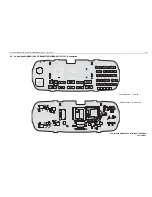
Страница 77: ...Professional Radio GM Series Controller Service Information Issue May 2007 ...
Страница 100: ...2 2 TROUBLESHOOTING CHARTS ...
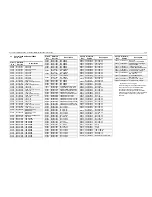
Страница 104: ...3 4 Controller schematics parts list ...
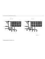
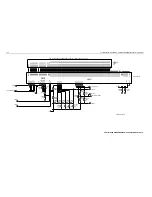
Страница 154: ...3 52 Controller T12 Schematic Diagrams ...
Страница 155: ...Professional Radio GM Series VHF 136 174MHz Service Information Issue May 2007 ...
Страница 164: ...1 6 MODEL CHART AND TECHNICAL SPECIFICATIONS ...
Страница 176: ...2 12 THEORY OF OPERATION ...
Страница 186: ...3 10 TROUBLESHOOTING CHARTS ...
Страница 190: ...4 4 VHF PCB SCHEMATICS PARTS LISTS ...
Страница 252: ...4 66 VHF 1 25W PCB 8471235L02 Schematics VHF 136 174 MHz IF ...
Страница 256: ...4 70 VHF 1 25W PCB 8471235L02 Schematics ...
Страница 257: ...Professional Radio GM Series UHF 403 470MHz Service Information Issue May 2007 ...
Страница 266: ...1 6 MODEL CHART AND TECHNICAL SPECIFICATIONS ...
Страница 349: ...Professional Radio GM Series LB1 29 6 36 0MHz LB2 36 0 42 0MHz LB3 42 0 50 0MHz Service Information Issue May 2007 ...
Страница 366: ...2 12 THEORY OF OPERATION ...
Страница 372: ...3 6 Low Band TROUBLESHOOTING CHARTS ...
Страница 376: ...4 4 Low band pcb schematics parts lists ...