


Chapter 3
SERVICE AIDS
1.0
Recommended Test Tools
Table 3-1 lists the service aids recommended for working on the radio. While all of these items are
available from Motorola, most are standard workshop equipment items, and any equivalent item
capable of the same performance may be substituted for the item listed.
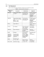
Table 3-1
Service Aids
Motorola Part
Number
Description
Application
RLN4460_
Portable Test Set
Enables connection to audio/accessory jack.
Allows switching for radio testing.
RKN4081_
Programming Cable with
Internal RIB
Includes radio interface box (RIB) capability.
RLN4853_
10 to 20 Pin Adapter
Connects RKN4081_ to the radio accessory
connector.
RKN4083_
Mobile Programming/Test
Cable
Connects radio to RIB (RLN4008_).
GTF374_
Program Cable
Connects RIB to Radio microphone input
RLN4008_
Radio Interface Box
Enables communications between radio and
computer’s serial communications adapter.
HLN8027_
Mini UHF to BNC Adaptor
Adapts radio antenna port to BNC cabling of
test equipment.
GPN6133_
Power Supply
Provides the radio with power when bench
testing.
EPN4040_
Wall-Mounted Power Supply
Used to supply power to the RIB (UK).
EPN4041_
Wall-Mounted Power Supply
Used to supply power to the RIB (Euro)
8180384J59
Housing Eliminator (short)
Test Fixture used to bench test the radio pcb
8180384L95
Housing Eliminator
(short + top)
Test Fixture used to bench test the radio pcb.
(Radio using pressure pads to retain pcb)
8180384J60
Housing Eliminator
(medium)
Test Fixture used to bench test the radio pcb
8180384J61
Housing Eliminator (long)
Test Fixture used to bench test the radio pcb
3080369B71
Computer Interface Cable
Connects the RIB to the Computer (25-pin)
3080369B72
Computer Interface Cable
Connects the RIB to the Computer 9-pin
(Use for IBM PC AT - other IBM models use
the B71 cable above)
6686119B01
Removal Tool
Assists in the removal of radio control head.
Содержание 6864115B62-C
Страница 1: ...Professional Radio GM Series Detailed Service Manual 6864115B62 C ...
Страница 2: ...ii ...
Страница 4: ...iv ...
Страница 5: ...Professional Radio GM Series Service Maintainability Issue July 2007 ...
Страница 8: ...ii ...
Страница 22: ...2 10 MAINTENANCE ...
Страница 25: ...Professional Radio GM Series Controlhead Service Information Issue July 2007 ...
Страница 77: ...Professional Radio GM Series Controller Service Information Issue May 2007 ...
Страница 100: ...2 2 TROUBLESHOOTING CHARTS ...
Страница 104: ...3 4 Controller schematics parts list ...
Страница 154: ...3 52 Controller T12 Schematic Diagrams ...
Страница 155: ...Professional Radio GM Series VHF 136 174MHz Service Information Issue May 2007 ...
Страница 164: ...1 6 MODEL CHART AND TECHNICAL SPECIFICATIONS ...
Страница 176: ...2 12 THEORY OF OPERATION ...
Страница 186: ...3 10 TROUBLESHOOTING CHARTS ...
Страница 190: ...4 4 VHF PCB SCHEMATICS PARTS LISTS ...
Страница 252: ...4 66 VHF 1 25W PCB 8471235L02 Schematics VHF 136 174 MHz IF ...
Страница 256: ...4 70 VHF 1 25W PCB 8471235L02 Schematics ...
Страница 257: ...Professional Radio GM Series UHF 403 470MHz Service Information Issue May 2007 ...
Страница 266: ...1 6 MODEL CHART AND TECHNICAL SPECIFICATIONS ...
Страница 349: ...Professional Radio GM Series LB1 29 6 36 0MHz LB2 36 0 42 0MHz LB3 42 0 50 0MHz Service Information Issue May 2007 ...
Страница 366: ...2 12 THEORY OF OPERATION ...
Страница 372: ...3 6 Low Band TROUBLESHOOTING CHARTS ...
Страница 376: ...4 4 Low band pcb schematics parts lists ...