


ii
Chapter 4 Low Band PCB/SCHEMATICS/PARTS LISTS
1.0 Allocation of Schematics and Circuit Boards ....................................................... 4-1
1.1 Controller Circuits ................................................................................................ 4-1
2.0 LB1 25-60W PCB 8486206B06 / Schematics ..................................................... 4-5
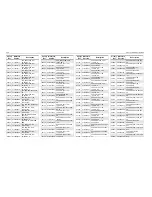
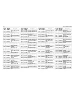
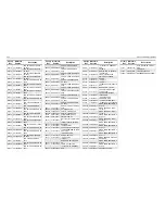
2.1 LB1 25-60W PCB 8486206B06 Parts List ......................................................... 4-15
3.0 LB2 25-60W PCB 8486207B05 / Schematics ................................................... 4-18
3.1 LB2 25-60W PCB 8486207B05 Parts List ......................................................... 4-28
4.0 LB3 25-60W PCB 8485908Z03 / Schematics.................................................... 4-31
4.1 LB3 25-60W PCB 8485908Z03 Parts List ......................................................... 4-41
5.0 LB1 25-60W PCB 8486206B08 / Schematics ................................................... 4-44
5.1 LB1 25-60W PCB 8486206B08 Parts List ......................................................... 4-48
6.0 LB2 25-60W PCB 8486207B07 / Schematics ................................................... 4-51
6.1 LB2 25-60W PCB 8486207B07 Parts List ......................................................... 4-53
7.0 LB3 25-60W PCB 8485908Z04 / Schematics.................................................... 4-56
7.1 LB3 25-60W PCB 8485908Z04 Parts List ......................................................... 4-58
8.0 LB3 25-60W PCB 8486908Z04 / Schematics.................................................... 4-61
8.1 LB3 25-60W PCB 8486908Z04 / Parts List ....................................................... 4-75
Содержание 6864115B62-C
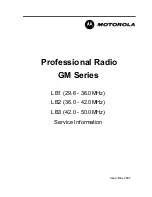
Страница 1: ...Professional Radio GM Series Detailed Service Manual 6864115B62 C ...
Страница 2: ...ii ...
Страница 4: ...iv ...
Страница 5: ...Professional Radio GM Series Service Maintainability Issue July 2007 ...
Страница 8: ...ii ...
Страница 22: ...2 10 MAINTENANCE ...
Страница 25: ...Professional Radio GM Series Controlhead Service Information Issue July 2007 ...
Страница 77: ...Professional Radio GM Series Controller Service Information Issue May 2007 ...
Страница 100: ...2 2 TROUBLESHOOTING CHARTS ...
Страница 104: ...3 4 Controller schematics parts list ...
Страница 154: ...3 52 Controller T12 Schematic Diagrams ...
Страница 155: ...Professional Radio GM Series VHF 136 174MHz Service Information Issue May 2007 ...
Страница 164: ...1 6 MODEL CHART AND TECHNICAL SPECIFICATIONS ...
Страница 176: ...2 12 THEORY OF OPERATION ...
Страница 186: ...3 10 TROUBLESHOOTING CHARTS ...
Страница 190: ...4 4 VHF PCB SCHEMATICS PARTS LISTS ...
Страница 252: ...4 66 VHF 1 25W PCB 8471235L02 Schematics VHF 136 174 MHz IF ...
Страница 256: ...4 70 VHF 1 25W PCB 8471235L02 Schematics ...
Страница 257: ...Professional Radio GM Series UHF 403 470MHz Service Information Issue May 2007 ...
Страница 266: ...1 6 MODEL CHART AND TECHNICAL SPECIFICATIONS ...
Страница 349: ...Professional Radio GM Series LB1 29 6 36 0MHz LB2 36 0 42 0MHz LB3 42 0 50 0MHz Service Information Issue May 2007 ...
Страница 366: ...2 12 THEORY OF OPERATION ...
Страница 372: ...3 6 Low Band TROUBLESHOOTING CHARTS ...
Страница 376: ...4 4 Low band pcb schematics parts lists ...