


2-12
THEORY OF OPERATION
informs the µP about the pressed PTT button. The µP will inform the host radio about any status
change on the PTT IRDEC line via SBEP bus.
When line PTT IRDEC is connected to FLT A+ level, transistor Q0851 is switched on through diode
VR0851 and thereby pulls the level on line ON OFF CONTROL to FLT A+ level. This switches on the
radio and puts the radio’s µP in bootstrap mode. Bootstrap mode is used to load the firmware into
the radio’s flash memory (See controller sub section for more details).
The HOOK input (J0811-3) is used to inform the µP when the microphone´s hang-up switch is
engaged. Dependent on the CPS programming the µP may take actions like turning the audio PA on
or off. While the hang up switch is open, line HOOK is pulled to +5 volts level by R0883. Transistor
Q0872 is switched on and causes a low at µP port PA1. When the HOOK switch is closed, signal
HOOK is pulled to ground level. This switches off R0883 and the resulting high level at µP port PA1
informs the µP about the closed hang up switch. The µP will inform the host radio about any status
change on the HOOK line via SBEP bus.
4.10
Speaker (Remote Mount Configuration only)
The remote mount controlhead contains a speaker for the receiver audio. The receiver audio signal
from the differential audio output of the audio amplifier located on the radio’s controller is fed via
connector J0801-10,11 to the speaker connector P0801 pin 1 and pin 2. The speaker is connected
to the speaker connector P0801. The controlhead speaker can be disconnected if only an external
speaker, connected on the accessory connector, should be used. If the controlhead is mounted
directly on the radio, an external speaker is required.
4.11
Electrostatic Transient Protection
Electrostatic transient protection is provided for the sensitive components in the controlhead by
diodes VR0811 - VR0814. The diodes limit any transient voltages to tolerable levels. The associated
capacitors provide Radio Frequency Interference (RFI) protection.
Содержание 6864115B62-C
Страница 1: ...Professional Radio GM Series Detailed Service Manual 6864115B62 C ...
Страница 2: ...ii ...
Страница 4: ...iv ...
Страница 5: ...Professional Radio GM Series Service Maintainability Issue July 2007 ...
Страница 8: ...ii ...
Страница 22: ...2 10 MAINTENANCE ...
Страница 25: ...Professional Radio GM Series Controlhead Service Information Issue July 2007 ...
Страница 77: ...Professional Radio GM Series Controller Service Information Issue May 2007 ...
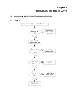
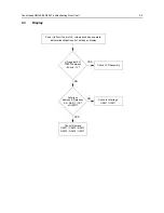
Страница 100: ...2 2 TROUBLESHOOTING CHARTS ...
Страница 104: ...3 4 Controller schematics parts list ...
Страница 154: ...3 52 Controller T12 Schematic Diagrams ...
Страница 155: ...Professional Radio GM Series VHF 136 174MHz Service Information Issue May 2007 ...
Страница 164: ...1 6 MODEL CHART AND TECHNICAL SPECIFICATIONS ...
Страница 176: ...2 12 THEORY OF OPERATION ...
Страница 186: ...3 10 TROUBLESHOOTING CHARTS ...
Страница 190: ...4 4 VHF PCB SCHEMATICS PARTS LISTS ...
Страница 252: ...4 66 VHF 1 25W PCB 8471235L02 Schematics VHF 136 174 MHz IF ...
Страница 256: ...4 70 VHF 1 25W PCB 8471235L02 Schematics ...
Страница 257: ...Professional Radio GM Series UHF 403 470MHz Service Information Issue May 2007 ...
Страница 266: ...1 6 MODEL CHART AND TECHNICAL SPECIFICATIONS ...
Страница 349: ...Professional Radio GM Series LB1 29 6 36 0MHz LB2 36 0 42 0MHz LB3 42 0 50 0MHz Service Information Issue May 2007 ...
Страница 366: ...2 12 THEORY OF OPERATION ...
Страница 372: ...3 6 Low Band TROUBLESHOOTING CHARTS ...
Страница 376: ...4 4 Low band pcb schematics parts lists ...