


Notes For All Schematics and Circuit Boards
2-5
5.0
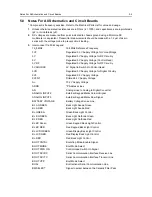
Notes For All Schematics and Circuit Boards
* Component is frequency sensitive. Refer to the Electrical Parts List for value and usage.
1.
Unless otherwise stated, resistances are in Ohms (k = 1000), and capacitances are in picofarads
(pF) or microfarads (µF).
2.
DC voltages are measured from point indicated to chassis ground using a Motorola DC
multimeter or equivalent. Transmitter measurements should be made with a 1.2 µH choke in
series with the voltage probe to prevent circuit loading.
3.
Interconnect Tie Point Legend:
16_8MHz
16.8MHz Reference Frequency
3V3
Regulated 3.3V Supply Voltage for Voice Storage
5V
Regulated 5V Supply Voltage for RF Circuitry
5V
Regulated 5V Supply Voltage (Control Head)
5V RF
Regulated 5V Supply Voltage for RF Circuitry
5V SOURCE
5V Signal to Switch On Control Head
5VD
Regulated 5V Supply Voltage for Digital Circuitry
9V3
Regulated 9.3V Supply Voltage
9V3FLT
Filtered 9.3V Supply Voltage
A+
13.2V Supply Voltage
ADDR
*P Address Lines
AN
Analog Lines to Analog to Digital Converter
ANALOG INPUT 2
External Keypad Matrix Column Signal
ANALOG INPUT 3
External Keypad Matrix Row Signal
BATTERY VOLTAGE
Battery Voltage Sense Line
BL A GREEN
Back Light Anode Green
BL A RED
Back Light Anode Red
BL GREEN
Green Back Light Control
BL K GREEN
Back Light Cathode Green
BL K RED
Back Light Cathode Red
BL KP Green
Green Keypad Back Light Control
BL KP RED
Red Keypad Back Light Control
BL LCD GREEN
Green Display Back Light Control
BL LCD RED
Red Display Back Light Control
BL RED
Red Back Light Control
BOOT CNTRL
Bootstrap Mode Enable Signal
BOOT MODE
Boot Mode Select
BOOT PWR ON
Control Head Switch On Signal
BOOT SCI RX
Serial Communication Interface Receive Line
BOOT SCI TX
Serial Communication Interface Transmit Line
BOOT VPP
Boot Mode Select
BUS+
Bi-directional Serial Communication Line
BWSELECT
Signal to select between the Ceramic Filter Pairs
Содержание 6864115B62-C
Страница 1: ...Professional Radio GM Series Detailed Service Manual 6864115B62 C ...
Страница 2: ...ii ...
Страница 4: ...iv ...
Страница 5: ...Professional Radio GM Series Service Maintainability Issue July 2007 ...
Страница 8: ...ii ...
Страница 22: ...2 10 MAINTENANCE ...
Страница 25: ...Professional Radio GM Series Controlhead Service Information Issue July 2007 ...
Страница 77: ...Professional Radio GM Series Controller Service Information Issue May 2007 ...
Страница 100: ...2 2 TROUBLESHOOTING CHARTS ...
Страница 104: ...3 4 Controller schematics parts list ...
Страница 154: ...3 52 Controller T12 Schematic Diagrams ...
Страница 155: ...Professional Radio GM Series VHF 136 174MHz Service Information Issue May 2007 ...
Страница 164: ...1 6 MODEL CHART AND TECHNICAL SPECIFICATIONS ...
Страница 176: ...2 12 THEORY OF OPERATION ...
Страница 186: ...3 10 TROUBLESHOOTING CHARTS ...
Страница 190: ...4 4 VHF PCB SCHEMATICS PARTS LISTS ...
Страница 252: ...4 66 VHF 1 25W PCB 8471235L02 Schematics VHF 136 174 MHz IF ...
Страница 256: ...4 70 VHF 1 25W PCB 8471235L02 Schematics ...
Страница 257: ...Professional Radio GM Series UHF 403 470MHz Service Information Issue May 2007 ...
Страница 266: ...1 6 MODEL CHART AND TECHNICAL SPECIFICATIONS ...
Страница 349: ...Professional Radio GM Series LB1 29 6 36 0MHz LB2 36 0 42 0MHz LB3 42 0 50 0MHz Service Information Issue May 2007 ...
Страница 366: ...2 12 THEORY OF OPERATION ...
Страница 372: ...3 6 Low Band TROUBLESHOOTING CHARTS ...
Страница 376: ...4 4 Low band pcb schematics parts lists ...