


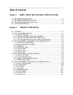


Chapter 2
THEORY OF OPERATION
1.0
Introduction
This Chapter provides a detailed theory of operation for the UHF circuits in the radio. For details of
the theory of operation and trouble shooting for the the associated Controller circuits refer to the
Controller Section of this manual.
2.0
UHF (403-470MHz) Receiver
2.1
Receiver Front-End
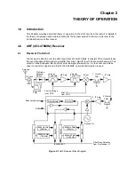
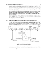
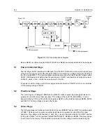
The receiver is able to cover the UHF range from 403 to 470 MHz. It consists of four major blocks:
front-end bandpass filters and pre-amplifier, first mixer, high-IF, low-IF and receiver back-end. Two
varactor-tuned bandpass filters perform antenna signal pre-selection. A cross over quad diode
mixer converts the signal to the first IF of 44.85 MHz. Low-side first injection is used.
Figure 2-1
UHF Receiver Block Diagram
Demodulator
1. Crystal
Filter
Mixer
Varactor
Tuned Filter
RF Amp
Varactor
Tuned Filter
Pin Diode
Antenna
Switch
RF Jack
Antenna
Control Voltage
from PCIC
First LO
from FGU
Recovered Audio
RSSI
Second LO
2. Crystal
Filter
455kHz Filter
(25kHz)
455kHz Filter
(25kHz)
455kHz Filter
(12.5kHz)
455kHz Filter
(12.5kHz)
Switch
Switch
Switch
Switch
Limiter
1. IF Amp
2. IF Amp
Filter Bank Selection
from Synthesizer IC
Harmonic
Filter
BWSELECT
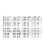
Содержание 6864115B62-C
Страница 1: ...Professional Radio GM Series Detailed Service Manual 6864115B62 C ...
Страница 2: ...ii ...
Страница 4: ...iv ...
Страница 5: ...Professional Radio GM Series Service Maintainability Issue July 2007 ...
Страница 8: ...ii ...
Страница 22: ...2 10 MAINTENANCE ...
Страница 25: ...Professional Radio GM Series Controlhead Service Information Issue July 2007 ...
Страница 77: ...Professional Radio GM Series Controller Service Information Issue May 2007 ...
Страница 100: ...2 2 TROUBLESHOOTING CHARTS ...
Страница 104: ...3 4 Controller schematics parts list ...
Страница 154: ...3 52 Controller T12 Schematic Diagrams ...
Страница 155: ...Professional Radio GM Series VHF 136 174MHz Service Information Issue May 2007 ...
Страница 164: ...1 6 MODEL CHART AND TECHNICAL SPECIFICATIONS ...
Страница 176: ...2 12 THEORY OF OPERATION ...
Страница 186: ...3 10 TROUBLESHOOTING CHARTS ...
Страница 190: ...4 4 VHF PCB SCHEMATICS PARTS LISTS ...
Страница 252: ...4 66 VHF 1 25W PCB 8471235L02 Schematics VHF 136 174 MHz IF ...
Страница 256: ...4 70 VHF 1 25W PCB 8471235L02 Schematics ...
Страница 257: ...Professional Radio GM Series UHF 403 470MHz Service Information Issue May 2007 ...
Страница 266: ...1 6 MODEL CHART AND TECHNICAL SPECIFICATIONS ...
Страница 349: ...Professional Radio GM Series LB1 29 6 36 0MHz LB2 36 0 42 0MHz LB3 42 0 50 0MHz Service Information Issue May 2007 ...
Страница 366: ...2 12 THEORY OF OPERATION ...
Страница 372: ...3 6 Low Band TROUBLESHOOTING CHARTS ...
Страница 376: ...4 4 Low band pcb schematics parts lists ...