23
TriStar MPPT-600V-TR Operator's Manual
Step 4 - Mounting to a Vertical Surface
The mounting location is important to the performance and operating life of the controller. The
environment must be dry and protected from water ingress. If required, the controller may be
installed in a ventilated enclosure with sufficient air flow. Never install the TS-MPPT-600V-TR in
a sealed enclosure. The controller may be mounted in an enclosure with sealed batteries, but
never with vented/flooded batteries. Battery fumes from vented batteries will corrode and destroy
the TS-MPPT-600V-TR circuits.
CAUTION: Risk of Burns
Install the TS-MPPT-600V-TR in a location that prevents casual contact. The TS-MPPT-600V-TR
heatsink can become very hot during operation.
ATTENTION : Risque de brûlures
Installez le TS-MPPT-600V-TR dans un endroit qui empêche le contact occasionnel. Le dissipateur de chaleur
TS-MPPT-600V-TR peut devenir très chaude pendant le fonctionnement.
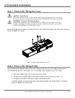
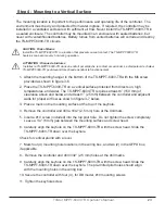
1. Attach the mounting hanger to the bottom of the TS-MPPT-600V-TR with the M6 screw
provided as shown in figure 3-6.
2. Place the TS-MPPT-600V-TR on a vertical surface protected from direct sun, high
temperatures, and water. The TS-MPPT-600V-TR requires at least 6” (150 mm) of
clearance above and below and at least 1” (25 mm) between the controller and adjacent
walls for proper air flow as shown in figure 3-7 below.
3.
Place a mark on the mounting surface at the top of the keyhole.
4. Remove the controller and drill a 3/32” (2.5 mm) hole at the drill mark.
5. Insert a #10 screw (included) into the top pilot hole. Do not tighten the screw completely.
Leave a 1/4” (6 mm) gap between the mounting surface and screw head.
6. Carefully align the keyhole on the TS-MPPT-600V-TR with the screw head. Slide the
TS-MPPT-600V-TR down over the keyhole.
Check for vertical plumb with a level.
7. Mark four (4) mounting hole locations in the wiring box, and two (2) in the GFPD box,
if applicable.
8. Remove the controller and drill 3/32” (2.5 mm) holes at the drill marks.
9. Carefully align the keyhole on the TS-MPPT-600V-TR with the screw head. Slide the
TS-MPPT-600V-TR down over the keyhole. The pre-drilled pilot holes should align
with the mounting holes in the wiring box.
10. Secure the controller with four (4), for DB model, #10 mounting screws.
11. Tighten the keyhole screw.


