background image

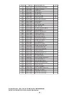
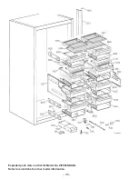
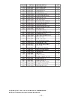
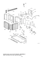
– 42 –

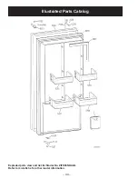
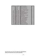
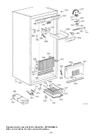
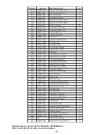
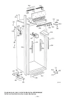
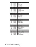
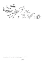
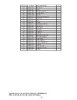
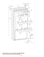
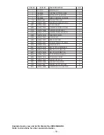
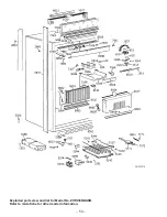
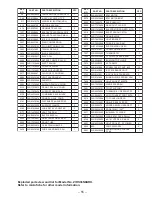
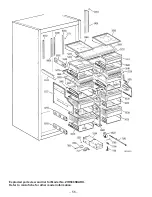
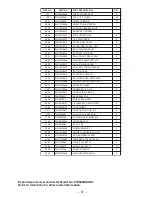
Exploded parts view and list for Model No. ZIFS36NDALH.
Refer to microfiche for other model information.

Содержание Monogram ZIFS36N RH

Страница 1: ...me Services Training GE Monogram 36 inch Refrigerator GE Monogram 36 inch Freezer ZIR36N LH All Fresh Food ZIR36N RH All Fresh Food ZIRS36N LH All Fresh Food ZIRS36N RH All Fresh Food ZIF36N LH All Freezer ZIF36N RH All Freezer ZIFS36N LH All Freezer ZIFS36N RH All Freezer ...

Страница 2: ...personal injury disconnect power before servicing this product If electrical power is required for diagnosis or test purposes disconnect the power immediately after performing the necessary checks RECONNECT ALL GROUNDING DEVICES If grounding wires screws straps clips nuts or washers used to complete a path to ground are removed for service they must be returned to their original position and prope...

Страница 3: ...Installation Highlights 3 Specifications 5 Nomenclature 7 Warranty Information 8 Operating Characteristics 10 Mechanical Disassembly 13 Troubleshooting 29 Component and Connector Locator Views 32 Schematics 35 Illustrated Parts Catalog 40 ...

Страница 4: ...r freezer was designed to provide the flexibility to harmonize with any kitchen cabinetry Decorative door insert panels allow it to match kitchen cabinets or blend with any kitchen decor Custom handles are also available to further personalize the refrigerator freezer Through a series of product and trim kit choices the Monogram refrigerator freezer can be beautifully integrated into the kitchen S...

Страница 5: ... See trim kit descriptions and appearance options in GE Publication 49 60055 Installation Instructions page 6 Semi Flush Installation These refrigerators can also be installed semi flush into an enclosure using the minimum cutout width The case trim creates a frame around the opening Side Panel Requirements Side panels are not required whenever the refrigerator is installed into an enclosure or be...

Страница 6: ... adapter where local codes permit a TEMPORARY CONNECTION may be made to a properly grounded two prong wall receptacle by the use of a UL listed adapter which is available at most hardware stores The larger slot of the adapter must be aligned to provide proper polarity in the connection of the power cord CAUTION Attaching the adapter ground terminal to the wall receptacle cover screw does not groun...

Страница 7: ... 5 Specifications ...

Страница 8: ... 6 ...

Страница 9: ...nclature Z I F S 3 6 N R H GE Monogram I Built in Configuration F Freezer R Refrigerator Fresh Food Energy S Stainless Steel Model Door Swing RH Right Hand LH Left Hand Icemaker N GE Non Icemaker Width Inches ...

Страница 10: ...aii and Washington D C In Alaska the warranty is the same except that it is LIMITED because you must pay to ship the product to the service shop or for the service technician s travel costs to your home All warranty service will be provided by our Factory Service Centers or by our authorized Customer Care servicers during normal working hours Should your appliance need service during warranty peri...

Страница 11: ... 9 Notes ...

Страница 12: ...porator fan circuit to the evaporator fan delay switch The door switch opens the evaporator fan switch circuit when the cabinet door is open The evaporator fan delay switch opens when the evaporator temperature has raised to 45 F and closes when the evaporator temperature has lowered to 25 F When closed the cabinet door switch and evaporator fan delay switch provide 115V to the evaporator fan Elec...

Страница 13: ... 11 GEA00637 Refrigerator Air Flow GEA00860 Freezer Air Flow ...

Страница 14: ... 12 Notes ...

Страница 15: ...Refrigerator and Freezer 16 Icemaker Freezer 17 Icemaker Water Valve and Water Line Freezer 17 To Replace the Water Valve 17 To Replace the Water Line from the Water Valve to the Fill Tube Grommet 18 Upper Light Shield Refrigerator and Freezer 19 Control Panel Refrigerator and Freezer 19 Upper Light Assembly Refrigerator and Freezer 20 Rear Duct Refrigerator and Freezer 20 Temperature Control Refr...

Страница 16: ...enter Divider 23 Evaporator Cover Refrigerator and Freezer 23 Defrost Heater Freezer Only 23 Evaporator Refrigerator and Freezer 24 Drain Pan Fan Refrigerator Only 24 Grille Panel Refrigerator and Freezer 25 Rocker Switches Refrigerator and Freezer 25 Defrost Control Freezer 26 PTCR Relay Overload Cover Refrigerator and Freezer 26 PTCR Relay Refrigerator and Freezer 26 Overload Refrigerator and Fr...

Страница 17: ...nserting a flat head screwdriver between the bottom edge of the wire guard and the hinge Note The plastic hinge cover is held by double sided adhesive tape 4 Remove the hinge cover 5 Remove T 20 Torx screws 3 securing the upper hinge to the top of the cabinet 6 Remove the hinge and bushing 7 Remove T 20 Torx screws 4 and the hinge from the door Door Closure Mechanism The door closure mechanism use...

Страница 18: ...Torx screws 3 base channel spacer and hinge from the underside of the cabinet GEA00663 Hinge Screws Hinge Hinge Pin Hinge Bushing Base Channel Spacer 3 Remove T 20 Torx screws 4 fastening the hinge to the bottom of the door 4 Remove the hinge Door Adjustment Be sure the top hinge does not hit the cabinet trim Adjust the door up or down by turning the threaded hinge pin on the bottom hinge Door Ass...

Страница 19: ...the freezer wall and remove To service the icemaker refer to GE Publication 31 4591 1985 Icemakers Icemaker Water Valve and Water Line Freezer The water valve is mounted under the cabinet beside the door closure mechanism The valve has a 1 4 in stub of copper tubing to provide a connection to the house water supply Refer to GE Publication 49 60055 GE Monogram 36 Refrigerators and 36 Freezers Custo...

Страница 20: ...reezer 2 Remove the unit from its installation see GE Publication 49 60055 GE Monogram 36 Refrigerators and 36 Freezers Custom Options Guide and Installation Instructions pages 12 17 3 Loosen 3 clamp screws 4 Loosen the clamp at the fill tube grommet Caution Do not lose the tubing sleeve when removing the water line from the fill tube grommet The sleeve must be used during reassembly to avoid leak...

Страница 21: ...el Refrigerator and Freezer 1 Remove the upper light shield see the previous procedure 2 Loosen do not remove 4 Phillips screws behind the panel GEA00653 Screws Screws Control Knob Control Knob Control Panel Control Panel 3 Pull the panel forward Note On the rear of the control panel is a small molded post which aligns the temperature control knob When reinstalling the control panel make certain t...

Страница 22: ... Screws Screws Screws Rear Duct Rear Duct Freezer GEA00627 Screws Screws Screws Screws Rear Duct Rear Duct Caution When removing and installing the rear duct insert a piece of plastic or card stock between the cover and the unit s side walls to avoid scratching the walls 3 Ease the rear duct away from the back wall Caution When reinstalling the rear duct be sure that the wires for the upper lights...

Страница 23: ...ntrol Bracket Bracket Wires Wires Screws Screws 7 Disconnect 2 wires from the temperature control if not already done Evaporator Fan Refrigerator and Freezer 1 Remove the icemaker freezer only upper light shield and rear duct see pages 17 20 2 Remove 2 screws from the fan motor bracket and carefully lower the evaporator fan assembly GEA00683 Screws Screws 3 Disconnect the wire connector from the f...

Страница 24: ...he bin from the sides Use a finger to pull up on the left release lever GEA00622 3 At the same time use a finger to push down on the right release lever GEA00623 4 While holding the levers slide the bin out To Remove the Showcase Lid 1 Remove 1 Phillips screw and plastic washer from the hinge pin in the center support GEA00624 Hinge Pin Screw Hinge Pin Screw 2 Grasp the showcase lid with both hand...

Страница 25: ...edure 2 Remove 4 Phillips screws from the evaporator cover 3 Pull the evaporator cover forward Disconnect wiring from lower light sockets 4 Remove the evaporator cover from cabinet GEA00633 Screws Screws Evaporator Cover Evaporator Cover GEA00635 Lower Light Sockets Lower Light Sockets Evaporator Evaporator Cover Evaporator Cover Defrost Heater Freezer Only Note The refrigerator does not have a de...

Страница 26: ...hold the evaporator to the cabinet and tilt the evaporator forward 9 Remove the defrost heater freezer only see the previous procedure 10 Desolder the capillary tube from the evaporator Caution To prevent damage to the capillary tube the capillary tube must be desoldered first Caution Protect cabinet wiring harness from heat during desoldering and resoldering Note It may be necessary to remove foa...

Страница 27: ...stall the drain pan and toekick Grille Panel Refrigerator and Freezer WARNING To avoid personal injury when servicing the components in the machine compartment stand on a ladder which will give enough support to allow removal of the top panel and safely allow access to service the unit 1 Place your thumbs under the left and right corners of the grille panel 2 Push up on the panel and pull it towar...

Страница 28: ...age 25 and vent guard 2 Insert a flat head screwdriver under the tab on the cover s top surface GEA00660 Tab Tab 3 Pry the cover up slightly while pulling it back to remove PTCR Relay Refrigerator and Freezer 1 Remove the grille panel see page 25 and vent guard 2 Remove the PTCR relay overload cover see the previous procedure 3 Pull the relay straight out from the compressor GEA00661 PTCR Relay PT...

Страница 29: ...move 1 Phillips screw and the run capacitor from the machine compartment Slide Out Chassis Refrigerator and Freezer The machine compartment contains the compressor and condenser on a slide out chassis that can be pulled out of the compartment to facilitate servicing the refrigeration system 1 Remove the grille panel see page 25 2 Remove the vent guard and wire guard 3 Remove 3 switches see page 25...

Страница 30: ... 28 Notes ...

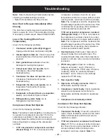
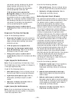
Страница 31: ...perature control or an open defrost control cooling mode terminals 3 and 4 are closed Note The compressor and the condenser fan should always operate at the same time If the condenser fan is operating the temperature control and defrost control are OK 115V not present at compressor overload Refrigerator Only If 115V is not present at the compressor overload check for an open temperature control or...

Страница 32: ... 1 Door switch open Check continuity across the door switch with the wires disconnected 2 Open wire or faulty connector Refer to Schematics and Strip Circuits Defrost System Check Freezer The automatic defrost function is controlled by the defrost thermostat switch and the defrost control The defrost control contains a motor cam mechanism that switches the defrost control between defrost mode and ...

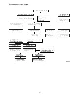
Страница 33: ...CTION PRESSURE ABOVE ZERO CONDENSER TEMPERATURE INCREASES THROUGHOUT NO CHANGE IN CONDENSER TEMPERATURE LOWER 2 3 SYSTEM HAS LEAK SYSTEM IS RESTRICTED Check high pressure joints with compressor running and condenser fan stopped FOUND LEAK NO LEAK FOUND REPAIR LEAK INSTALL DRYER AND RECHARGE CHECK EVAPORATOR FOR LEAKS Check low pressure joints with compressor stopped and defrost heaters energized F...

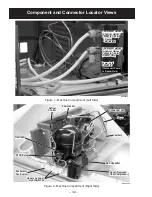
Страница 34: ...t Control Overload Overload PTCR Relay PTCR Relay Evaporator Fan Switch Evaporator Fan Switch Upper and Lower Light Switches Upper and Lower Light Switches GEA00659 Power Cord Connector Power Cord Connector Compressor Harness to Cabinet Harness Connector 6 pin Freezer Only Compressor Harness to Cabinet Harness Connector 6 pin Freezer Only Compressor Harness to Cabinet Harness Connector 9 pin Freez...

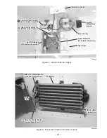
Страница 35: ...rator Inside of Cabinet Lower GEA00685 Cabinet Harness to Upper Interior Harness Connector Cabinet Harness to Upper Interior Harness Connector Upper Interior Harness to Light Assembly Connector Upper Interior Harness to Light Assembly Connector Temperature Control Temperature Control Capillary Temperature Control Capillary Temperature Control Evaporator Fan Evaporator Fan Upper Light Upper Light L...

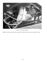
Страница 36: ...hows the underside of the unit with the door closure mechanism removed GEA00665 Auxiliary Evaporation Fan Auxiliary Evaporation Fan Icemaker Water Tubing Icemaker Water Tubing Water Valve Water Valve Figure 5 Underside of Cabinet ...

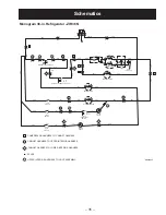
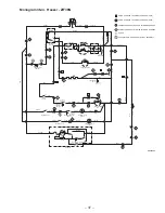
Страница 37: ...ENSER FAN DRAIN PAN FAN FAN SWITCH UPPER LIGHT SWITCH LOWER LIGHT SWITCH LOWER LIGHTS UPPER LIGHTS S BLACK BLACK ORN ORN ORN ORN 0 5 ORN O R N ORN ORN BLU YEL YEL YEL YEL YEL YEL BLU ORN ORN ORN ORN COMPRESSOR HARNESS TO CABINET HARNESS CABINET HARNESS TO UPPER INTERIOR HARNESS CABINET HARNESS TO LOWER INTERIOR HARNESS SPLICE UPPER INTERIOR HARNESS TO LIGHT ASSEMBLY CL OP CL OP PTCR DEFROST THERMO...

Страница 38: ... ORN ORN ORN ORN ORN 3 5 4 4 3 1 2 4 CL OP LIGHT THERMOSTAT SWITCH GEA00605 L1 BRN BRN BRN BLK BLK RED OVERLOAD COMPRESSOR RED 1 2 3 RED RED RED GRAY GRAY BLK BLK 3 42 BRN BRN NEUTRAL 176 2 9 46 5 5 10 C R RUN CAPACITOR FAN SWITCH S BLACK BLACK ORN ORN ORN ORN 0 5 ORN O R N BLU BLU ORN ORN ORN ORN ORN 3 1 1 2 3 2 3 4 4 2 5 4 8 CL OP PTCR RELAY CONDENSER FAN DEFROST THERMOSTAT SWITCH DRAIN PAN FAN ...

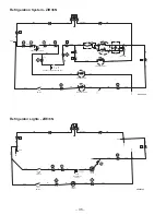
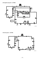
Страница 39: ...2 1 4 6 2 5 3 1 4 1 9 7 6 2 8 5 3 CABINET HARNESS TO UPPER INTERIOR HARNESS CABINET HARNESS TO LOWER INTERIOR HARNESS SPLICE 176 46 80 590 46 38 1 1 3 1 2 2 4 3 C R S RED RED RED RED RED RED RED RED RED RED HOLD BLACK BLACK WHITE BROWN MOLD WATER ICEMAKER MOTOR BROWN BROWN BROWN BROWN FREEZER DOOR FREEZER DOOR BLUE FZ FAN SWITCH BLUE BLUE BLUE BLUE BLUE BLUE YEL YEL YEL GRAY GRAY YELLOW DEFROST CO...

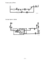
Страница 40: ...45 OP 4 3 5 3 4 4 6 3 4 1 5 3 1 2 GEA00600 L1 BROWN BRN BRN BRN BRN BRN TEMPERATURE CONTROL NEUTRAL ORANGE ORANGE ORANGE ORANGE EVAPORATOR FAN ORN ORN ORN ORANGE CONDENSER FAN COMPRESSOR OVERLOAD RUN CAPACITOR BLACK BLACK BLACK BLACK ORANGE ORANGE ORANGE ORANGE 2 9 5 5 10 176 46 1 1 3 1 2 2 4 3 C R S RED RED RED RED RED RED RED RED FZ FAN SWITCH BLUE BLUE BLUE BLUE BLUE BLUE GRAY GRAY YELLOW DEFRO...

Страница 41: ... 46 RED RED HOLD BLACK BLACK WHITE BROWN MOLD WATER ICEMAKER MOTOR BROWN BROWN L1 N BLUE T C O THERMOSTAT FEELER ARM O R N 3 2 2 1 4 7 6 3 GEA00601 BRN ORANGE ORANGE YELLOW YELLOW YELLOW YELLOW FREEZER LIGHTS UPPER FREEZER LIGHTS LOWER ORN ORANGE ORANGE ORANGE BROWN BROWN L1 N FREEZER DOOR FREEZER DOOR 130 190 O R N 6 1 5 CL OP 3 4 LIGHT THERMOSTAT SWITCH ...

Страница 42: ... 40 Illustrated Parts Catalog Exploded parts view and list for Model No ZIFS36NDALH Refer to microfiche for other model information ...

Страница 43: ... X 1 0 R W M I H S E G N I H 1 0 8 2 5 1 4 4 0 1 X 2 0 R W E G N I H F F T U N P O T S R O O D 1 8 7 3 5 5 6 1 0 1 X 2 0 R W S S F F O D N A T S 2 1 9 3 5 8 3 1 0 1 X 1 7 R W W O D N I W W R O O D F F N I B 8 6 0 4 5 9 3 1 0 1 X 1 7 R W H R P E E D F F R O O D N I B 1 7 0 4 5 0 4 1 0 1 X 1 7 R W H L P E E D F F R O O D N I B 1 3 0 0 6 5 2 3 0 1 X 8 7 R W S S H L M S A R O O D Z F F F 1 6 0 5 6 0 2...

Страница 44: ... 42 Exploded parts view and list for Model No ZIFS36NDALH Refer to microfiche for other model information ...

Страница 45: ... S N E D N O C 1 0 4 1 5 4 7 6 0 1 X 7 1 R W D N O C X U A N A P N I A R D 1 1 4 1 5 0 8 1 0 1 X 1 0 R W T R O P P U S N A P R E N E T S A F 2 2 4 1 5 5 2 5 0 1 X 2 0 R W S P M A L C T R O P P U S 2 6 6 1 5 5 4 0 0 1 X 1 0 R W R E T A E H P A V E T E R E R I W 2 7 9 1 5 5 4 1 0 1 X 2 0 R W H L P A V E E L F F A B 2 0 5 3 5 5 5 6 0 1 X 7 1 R W E B U T N I A R D 1 6 8 5 5 0 7 6 0 X 3 1 R W H L M S A...

Страница 46: ... 44 Exploded parts view and list for Model No ZIFS36NDALH Refer to microfiche for other model information ...

Страница 47: ...2 0 1 9 8 8 2 7 1 3 8 1 X 1 0 R W G T M E L L I R G W E R C S 2 7 1 3 7 6 4 0 3 X 7 1 R W N O L Y N P M A L C 4 1 4 9 6 5 7 7 8 5 8 X 2 0 R W E G N I H P O T G N I H S U B 1 2 5 7 7 5 4 8 1 X 1 0 R W 0 0 9 T H O T T 4 2 2 1 W E R C S 2 1 0 6 7 7 0 0 9 1 X 1 0 R W T U N L E R R A B 6 1 5 2 3 8 4 3 6 7 7 1 0 9 1 X 1 0 R W S M S S U R T L I H P 4 1 2 3 8 6 5 3 8 7 0 8 0 0 1 X 3 1 R W H L R E V O C E ...

Страница 48: ... 46 Exploded parts view and list for Model No ZIFS36NDALH Refer to microfiche for other model information ...

Страница 49: ...3 X 8 1 8 W E R C S 2 0 0 5 5 0 4 0 0 1 X 4 1 R W D I L E S A C W O H S T N O R F L A E S 2 4 9 5 5 1 7 6 0 X 3 1 R W H R M S A E S A B 1 0 2 6 5 7 7 3 8 X 2 0 R W M S A R A E R L E E H W 2 7 2 0 6 2 1 0 0 1 X 1 2 R W R E P P U M S A T E K S A B G E V 2 8 2 0 6 0 2 1 0 1 X 2 3 R W M S A T E K S A B K C A N S 2 8 3 5 6 1 2 1 0 1 X 2 3 R W R E W O L M S A T E K S A B G E V 4 5 5 0 7 8 7 4 0 1 X 2 0 ...

Страница 50: ... 48 Exploded parts view and list for Model No ZIFS36NDALH Refer to microfiche for other model information ...

Страница 51: ...5 X 1 0 R W R E H S A W 4 3 6 3 2 4 8 6 5 X 1 0 R W E P Y T S S L I H P 8 3 X 2 3 6 2 6 0 5 4 5 4 6 0 1 X 7 1 R W N A P N O I T A R E G I R F E R 1 9 5 5 5 5 4 0 3 X 7 1 R W G F W T N O R F E L F F A B 1 3 7 5 5 0 1 6 8 X 2 0 R W G I R F E R T N U O M E D I L S 2 1 4 6 5 6 3 5 0 1 X 2 0 R W R E N I A T E R N A P M E T S Y S 1 3 0 1 6 7 3 5 0 1 X 2 0 R W G T M D N O C T K R B 2 6 0 1 6 8 7 6 0 1 X ...

Страница 52: ... 50 Exploded parts view and list for Model No ZIFS36NDALH Refer to microfiche for other model information ...

Страница 53: ... 2 R W R O T A L U S N I 1 3 6 8 3 8 1 5 X 9 2 R W R E V E L M R A 1 4 6 8 3 8 1 0 X 9 2 R W G N I S U O H 1 5 6 8 0 6 1 0 X 9 2 R W R E P P I R T S 1 6 6 8 4 7 1 5 X 9 2 R W R O T C E J E 1 7 6 8 3 5 1 0 X 9 2 R W P U C L L I F T E L N I G N R B 1 8 6 8 4 0 2 0 X 9 2 R W M S A R E T A E H D L O M 1 9 6 8 7 5 1 0 X 9 2 R W T A T S O M R E H T 1 0 7 8 6 8 1 0 X 9 2 R W S S E N R A H E R I W 1 1 7 8...

Страница 54: ... 52 Exploded parts view and list for Model No ZIRS36NDARH Refer to microfiche for other model information ...

Страница 55: ...1 0 1 X 1 0 R W M T B R O O D W E R C S E G N I H 3 0 8 1 5 2 4 1 0 1 X 1 7 R W P M O C Y R I A D M S A 1 4 8 1 5 4 5 0 0 1 X 1 0 R W M I H S E G N I H 1 8 0 2 5 7 0 0 0 1 X 2 2 R W M S A Y R I A D L A E S 1 0 8 2 5 1 4 4 0 1 X 2 0 R W E G N I H F F T U N P O T S R O O D 1 8 7 3 5 5 6 1 0 1 X 2 0 R W S S F F O D N A T S 2 1 9 3 5 8 3 1 0 1 X 1 7 R W W O D N I W W R O O D F F N I B 4 6 0 4 5 9 3 1 ...

Страница 56: ... 54 Exploded parts view and list for Model No ZIRS36NDARH Refer to microfiche for other model information ...

Страница 57: ... 7 1 R W E B U T N I A R D 1 7 3 4 5 6 1 0 0 1 X 8 0 R W S S M B H L M I R T E S A C 1 8 3 4 5 8 6 1 0 1 X 2 0 R W H R S S M B D R A U G E R I W 1 F E R O N O N T R A P N O I T P I R C S E D T R A P Y T Q 0 7 5 5 7 3 0 0 1 X 0 6 R W R O T O M M T B 1 4 7 5 5 3 4 4 0 1 X 2 0 R W T K R B R O T O M M T B 1 6 8 5 5 0 7 6 0 X 3 1 R W H L M S A E S A B 1 8 0 0 6 8 5 6 0 1 X 7 1 R W F F D S 6 3 T C U D R...

Страница 58: ... 56 Exploded parts view and list for Model No ZIRS36NDARH Refer to microfiche for other model information ...

Страница 59: ... L G N O T T U B 4 7 2 2 5 3 1 0 0 1 X 2 7 R W H L E D I L S T R O P P U S 1 9 2 2 5 3 1 0 0 1 X 4 1 R W S S A L G N A P G E V R A E R L A E S 1 2 3 2 5 8 4 0 0 1 X 1 0 R W T O V I P E S A C W O H S G N I H S U B 2 3 1 4 5 8 7 0 0 1 X 2 3 R W M S A N A P K C A N S 2 1 2 4 5 0 5 0 0 1 X 1 0 R W 4 3 X 8 1 8 W E R C S 2 6 3 4 5 7 1 0 0 1 X 8 0 R W S S M B H R M I R T E S A C 1 4 9 5 5 1 7 6 0 X 3 1 R...

Страница 60: ... 58 Exploded parts view and list for Model No ZIRS36NDARH Refer to microfiche for other model information ...

Страница 61: ...M A O F E L F F A B P O T D N O C 1 0 3 3 1 6 1 7 1 X 1 0 R W R O T O M N A F W E R C S 3 1 5 5 1 5 4 6 5 X 1 0 R W S M S H P 2 1 X 0 1 5 4 2 5 5 1 1 8 0 8 X 2 0 R W L I H P H P S M S 8 3 X 0 1 9 5 6 5 1 4 4 0 0 1 X 1 0 R W T U N X E H 0 2 4 1 4 6 6 5 1 2 0 7 5 X 1 0 R W R E H S A W 4 3 6 3 2 4 8 6 5 X 1 0 R W E P Y T S S L I H P 8 3 X 2 3 6 2 6 0 5 4 5 4 6 0 1 X 7 1 R W N A P N O I T A R E G I R ...

Страница 62: ... 60 Notes ...
Отзывы: