background image

AQUILA ALLIANCE

Code 4-121149A - 11/2017

Manuale d’uso

Operator’s manual

Manuel d’utilisation

Betriebsanleitung

Manual de uso

[email protected]

www.mondolfoferro.it

Содержание Aquila Alliance

Страница 1: ...AQUILA ALLIANCE Code 4 121149A 11 2017 Manuale d uso Operator s manual Manuel d utilisation Betriebsanleitung Manual de uso info mondolfoferro it www mondolfoferro it...

Страница 2: ...sia sempre in condizioni ottimali di esercizio Nel caso incuisiosservinoeventualimalfunzionamentioprobabilisituazionidipericolo arrestare immediatamente lo smontagomme e porre rimedio a tali condizio...

Страница 3: ...ciato Ruote a canale cieco Stallonatura Ruote standard Ruote ribassate Smontaggio Ruote standard con leva tallone e protezione manicotto in plastica Sistemazione in sede completa della testina per evi...

Страница 4: ...________________________________________________________________ _____________________________________________________________________ _________________________________________________________________...

Страница 5: ...CERCHIO PNEUMATICO 19 1 4 USO PREVISTO DELLA MACCHINA 19 1 5 FORMAZIONE DEL PERSONALE 19 1 6 CONTROLLI PRELIMINARI 19 1 7 DURANTE L UTILIZZO 20 2 TRASPORTO STOCCAGGIO E MOVIMENTAZIONE 20 3 SBALLATURA...

Страница 6: ...IO PNEUMATICI 44 6 9 a Indicazioni di sicurezza 44 6 9 b Gonfiaggio dei pneumatici 46 6 9 c Procedura speciale 47 6 10 SBLOCCAGGIO E SCARICO 49 7 RICERCA GUASTI 50 8 MANUTENZIONE 52 9 INFORMAZIONI SUL...

Страница 7: ...tura le procedure e la manutenzione Il corsivo utilizzato per fare riferimento a parti specifiche del presente manuale che offrono informazioni aggiuntive o chiarimenti Taliriferimentidevonoesserelett...

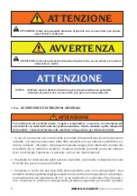
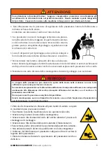
Страница 8: ...o per riferimento futuro ATTENZIONE 1 In caso di esecuzione non corretta delle procedure di manutenzione fornite nel presente manuale o di mancata osservanza delle altre istruzioni in esso contenute p...

Страница 9: ...dello stesso incorporato nel fianco non corrisponde esattamente alla dimensione del cerchio stampata all interno del cerchio o se il cerchio o lo pneumatico sono difettosi Non superare mai la pressio...

Страница 10: ...ON installare o gonfiare pneumatici tagliati danneggiati marci o logori NON installare pneu matici su cerchi lesionati piegati arrugginiti logori deformati o danneggiati 15 Qualora lo pneumatico doves...

Страница 11: ...o per eseguire qualsiasi riparazione della macchina in sicurezza nel caso in cui l utente abbia tentato di eseguire la riparazione 24 L utente deve riporre particolare attenzione alle avvertenze degli...

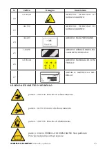
Страница 12: ...SI CUREZZA 13 4 121151 ADESIVO ALLIANCE 14 468506 ADESIVO AUTOMATIC 15 446388 ADESIVO RETEDIALIMENTA ZIONE CORRETTA 16 4 113355 ADESIVO MANUTENZIONE FILTRO 17 35023276 ADESIVO PERICOLO DI ESPLOSIONE...

Страница 13: ...103648 ADESIVO MANIGLIA DI CON TROLLO 27 ISO9001 Code Serial N X XXXXXXXX XX XX XXXXXXXXX QUAL SYS CERTIFIED ANNO DI COSTRUZIONE MANUFACTURED Mod V A kW Hz Ph bar7psi Port max ADESIVO MATRICOLA MO DE...

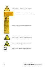
Страница 14: ...5211A Pericolo di scossa elettrica parte n 35024870 Istruzioni di sicurezza parte n 3502376 Pericolo di schiacciamento parte n 4 204190 Pericolo di schiacciamento parte n 446435 Pericolo di schiacciam...

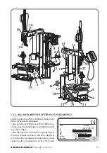
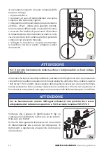
Страница 15: ...tatarghettadati macchina Fig 1 alla distanza tra la macchina operatrice ed il punto di allacciamento alla rete elettrica in modo che la caduta di tensione a pieno carico risulti non superiore al 4 10...

Страница 16: ...rarsi che la pressione disponibile e le prestazioni dell impianto ad aria compressa siano compatibiliconquellenecessariealcorrettofunzionamentodellamacchina vederelasezione Dati tecnici Per il corrett...

Страница 17: ...a massima pneumatico 15 381 mm Autocentrante posizionamento degli utensili rispetto al cerchione manuale lato in appoggio flangiato centraggio su cono bloccaggio pneumatico automatico sistema di trasm...

Страница 18: ...PRESSIONI DELL ARIA La macchina dotata di una valvola limitatrice di pressione interna per ridurre il rischio di gonfiaggio eccessivo dello pneumatico PERICOLO DI ESPLOSIONE Non superare mai la pressi...

Страница 19: ...nuten zione del tipo di ruota sulla quale stanno intervenendo e alle procedure operative di sicurezza Le informazioni da utilizzare nel programma di formazione includono come minimo le infor mazioni p...

Страница 20: ...chiudendo la valvola di intercetta zione innesto rapido 2 TRASPORTO STOCCAGGIO E MOVIMENTAZIONE Condizioni trasporto macchina Comprensione della necessit di stare lontani dallo smontagomme durante il...

Страница 21: ...eggiamenti alla macchina e pregiudicare la sicurezza dell operatore ATTENZIONE Prima di togliere la macchina dal pallet assicurarsi che dallo stesso siano stati rimossi gli elementi mostrati qui di se...

Страница 22: ...allare la macchina conformemente a tutte le norme sulla sicurezza applicabili incluse ma non limitate ad esse quelle emesse da OSHA PERICOLO DI ESPLOSIONE O DI INCENDIO Non utilizzare la macchina in a...

Страница 23: ...ebloccataeperfettamente centrata sul dispositivo autocentrante Le operazioni di carico e scarico ruota sono facilitate da un ergonomico sollevatore kit opzionale che riduce lo sforzo dell operatore La...

Страница 24: ...ico della ruota dalla posizione di lavoro Grazie a questa macchina inoltre possibile raggiungere i seguenti obiettivi Ridurre lo sforzo fisico dell operatore Salvaguardia cerchio e pneumatico Ogni mac...

Страница 25: ...IONI D INGOMBRO MM Lunghezza min 1235mm max 1784mm Larghezza min 928mm max 2018mm Altezza min 1210 mm max 2224 mm 2224 max 1784 max 2018 max 9 5 3 COMPONENTI DELL ATTREZZATURA PRINCIPALI ELE MENTI DI...

Страница 26: ...le 5 Cilindro comando utensile smontaggio 6 Cilindro per discesa torretta mobile 7 Consolle 8 Gruppo appoggio e centraggio ruota 9 Maniglia comando bloccaggio 10 Gruppo stallonatore 11 Disco stallonat...

Страница 27: ...AQUILA ALLIANCE Manuale operatore 27 15 1 12 13 14 2 18 3 8 9 5 6 7 10 11 4 17 23 20 24 22 21 10 A B C...

Страница 28: ...si aziona la leva 21 verso l alto si allontana il disco stallonatore dal cerchio si ottiene la di sattivazione del disco stallonatore 6 Pulsante comando penetrazione disco stallonatore inferiore prem...

Страница 29: ...mento L operazione successiva al ribaltamento deve essere effettuata in posizione di lavoro A ATTENZIONE FARE ATTENZIONE AD EVENTUALI LESIONI Prima di lavorare sulla macchina Scollegare l alimentazion...

Страница 30: ...approvati dagli standard del DOT Department of Transportation Dipar timento dei trasporti La sigla DOT certifica la conformit del pneumatico agli standards di sicurezza adottati da Stati Uniti e Canad...

Страница 31: ...IZZODIACCESSORI PER CENTRAGGIO E BLOCCAGGIO SECONDO IL TIPO DI CERCHIO nel presente manuale Il dispositivo TPMS opzionale pu essere utilizzato esclusivamente per verificare il corretto funzionamento d...

Страница 32: ...te B Avvicinare manualmente il cono di centraggio al cerchione agendo sui fermi 1 C Serrare il dispositivo di bloccaggio ruotando le maniglie 2 in senso orario D 6 4 SGONFIAGGIO PNEUMATICO fig 16 Sgon...

Страница 33: ...il gruppo stallonatore dalla po sizionediriposoallaposizionedilavoro b Avvicinare il disco al cerchio c Lo spostamento orizzontale si esegue manualmente ruotando la consolle d Ilmovimentoverticalevien...

Страница 34: ...e almeno una rotazione completa per ottenere la completa stallonatura E con sigliato ingrassare il tallone del cerchio durante la rotazione d Riportare con comando 2 Fig 10 il braccio superiore verso...

Страница 35: ...ciamentodellopneumatico di 5 mm circa Azionare la penetrazione del disco comando 6 Fig 10a e successivamente avvia re la rotazione della ruota comando a pedale 15 Fig 10 contemporaneamente si abbassa...

Страница 36: ...endo la pressione del disco stallonatore sul pneumatico Fig 22 creare lo spazio sufficiente per consentire il capovolgimento dell utensile di smon taggio Utilizzando il comando 23 Fig 21 capovolgere l...

Страница 37: ...nsolita possono causare lo scivolamento del pneumatico sul cerchio rendendo difficile lo smontaggio In primo luogo provare a utilizzare il disco stallonatore verso l alto per sollevare il pneumatico A...

Страница 38: ...fino a portarlo a livello del tallone superiore del cerchione A B Fig 24 Ottenere la penetrazione del disco tenendo premuto il tasto 6 Fig 10a C Fig 24 Avviare la rotazione della ruota pedale 15 Fig...

Страница 39: ...llone inferiore con il braccio superiore per cerchi rovesci Nel caso di cerchi rovesci la portata della macchina pu essere aumentata utilizzando il gruppo stallonatore superiore per estrarre il tallon...

Страница 40: ...eriore totalmente verso il basso 3 Fig 10a Aprire lo stallonatore 7 Fig 10a e smontare il pneumatico Inclinare all indietro la colonna pe dale 13 Fig 10 e rimuovere il pneumatico Qualsiasi rumore prod...

Страница 41: ...ito deformazioni non presentino i fori di fissaggio ovalizzati non siano incrostati o arrugginiti e non abbiano bave taglienti sui fori della valvola Assicurarsi che la copertura sia in buono stato e...

Страница 42: ...o del tallone B Ruotare fino al completo montaggio Posizionamento del tallone superiore Fig 26c Posizionare il tallone superiore del pneuma tico come chiaramente mostrato in Fig 26c Fare attenzione ch...

Страница 43: ...e Avviare di nuovo la rotazione pedale 15 Fig 10 finoaportareilmorsettoinprossimit del discostallonatoreesmontareilmorsetto Fig 26e Dopo aver completato il montaggio sollevare il disco stallonatore co...

Страница 44: ...o PERICOLO Rispettare sempre le normative nazionali in materia di sicurezza che possono essere ulteriormente restrittive rispetto a quanto indicato nel presente manuale secondo il principio per cui la...

Страница 45: ...pio non montare mai uno pneumatico da 16 su un cerchio da 16 5 o vice versa moltopericoloso Pneumaticiecerchinoncorrispondenti potrebbero esplodere provocando incidenti 3 Non oltrepassare mai la press...

Страница 46: ...operazione evitare di distrarsi e controllare continuamente la pressione dellopneumaticosulmanometro 17 Fig 10 alfine di evitare un gonfiaggio eccessivo Il gonfiaggio dei pneumaticitubelessrichiedeun...

Страница 47: ...umatico montato sia serrata saldamente sul piatto auto centrantepermezzodellamanigliadicentraggio Fig 29 2 Togliereilnucleodellostelodellavalvolaqualora non fosse gi stato rimosso Fig 29a 3 Collegare...

Страница 48: ...sima ammessa dal costruttore la ruota deve essere rimossa dallo smontagomme posta in una gabbia di gonfiaggio e gonfiata secondo le istruzioni del costruttore Reinstallare il meccanismo valvola nello...

Страница 49: ...ottone ubicato sotto il manometro della pressione dell aria Scollegare il tubo di gonfiaggio dallo stelo della valvola Togliere la ruota dallo smontagomme 6 10 SBLOCCAGGIOESCARICO Sbloccaggio ruota da...

Страница 50: ...uppo stallonatore non funziona Traslazione verticale assente Controllare che non vi siano tubi piegati Verificare il funzionamento della valvola di sollevamento abbassamento Controllare che non vi sia...

Страница 51: ...rata Registrare piastrina Calibrare nuovamente Lo scivolo verticale ha difficolt a sollevarsi Piastrina bloccaggio difettosa Sostituire le piastra Piastrina bloccaggio non registrata Registrare piastr...

Страница 52: ...tto Pezzi di ricambio non autorizza l utente ad intervenire sulle macchine ad esclusione di quanto esplicitamente descritto nel manuale d uso ma consente all utente di fornire informazioni precise all...

Страница 53: ...ta possono rimanere sotto pressione Prima di procedere con qualsiasi operazione di manutenzione o rabbocco lubrificante scollegare la macchina dalla linea di alimentazione pneumatica La MONDOLFO decli...

Страница 54: ...er effettuare le operazioni di manutenzione dopo un lungo periodo di utilizzo Se un funzionamento manuale non sufficiente utilizzare il tasto specifico previsto Fig 40e Pulire con panno asciutto Evita...

Страница 55: ...sterno con cui il prodotto fornito e smaltire in modo adeguato le batterie usate solo se contenute nel prodotto Con il vostro aiuto si pu ridurre la quantit di risorse naturali impiegate per la realiz...

Страница 56: ...MEZZI ANTI INCENDIO DA UTILIZZARE Per la scelta dell estintore pi adatto consultare la tabella seguente Materiali secchi Liquidi infiammabili Apparecchiature elettriche Idrico SI NO NO Schiuma SI SI N...

Страница 57: ...inclinate e sono disposte in modo che i fili costituenti una tela s incrocino con quelli della tela adiacente Il battistrada che la parte dello pneumatico a contatto con il terreno solidale ai fianch...

Страница 58: ...terno del battistrada in contatto con la cintura oppure se quest ultima non presente pneumatici convenzionali con l ultima tela della carcassa 13 Spalla E la zona estrema del battistrada compresa tra...

Страница 59: ...tata di valvola che contiene aria pressurizzata Valvola Lavalvola undispositivomeccanicochepermette il gonfiaggio sgonfiaggio e la tenuta dell aria in pressione all internodiunacamerad aria odiunacope...

Страница 60: ...e Cerchio senza foro centrale E Cerchio per furgone D Cerchio a canale rovescio C Cerchio standard A Cerchio con foro incassato B SCHEMA UTILIZZO ACCESSORI DI CENTRAGGIO E BLOCCAGGIO PER TIPOLOGIA DI...

Страница 61: ...AQUILA ALLIANCE Manuale operatore 61 M9 M2 M15 M4 M10 M13 M14 M7 M11 Accessori a richiesta...

Страница 62: ...62 AQUILA ALLIANCE Manuale operatore M13 M14 M11 M7 M2 M9 A...

Страница 63: ...AQUILA ALLIANCE Manuale operatore 63 M6 M5 M11 M7 M9 B...

Страница 64: ...64 AQUILA ALLIANCE Manuale operatore C M11 M10 M2 M15 M9 D...

Страница 65: ...AQUILA ALLIANCE Manuale operatore 65 E...

Страница 66: ...66 AQUILA ALLIANCE Manuale operatore F...

Страница 67: ...CHEMA ELETTRICO GENERALE XS1 Presa di alimentazione AP1 Scheda motore singola doppia M1 Motore SQ1 Microinterruttore doppia velocit SQ2 Microinterruttore rotazione in SENSO ANTIORARIO SQ3 Microinterru...

Страница 68: ...DRO RIBALTAMENTO PALO 11 Valvola 5 2 NA 12 Cilindro ribalto F COMANDO CILINDRO MOVIMENTO UTENSILE 13 Valvola 5 2 NA 14 Cilindro movimento utensile G PEDALI 15 Valvola 3 2 NC 16 Valvola 3 2 NA 17 Valvo...

Страница 69: ...AQUILA ALLIANCE Manuale operatore 69...

Страница 70: ...Notes 70...

Страница 71: ...e sure that your Tyre Changer is in optimum working order If you suspect that anything is not working properly or that a dangerous situation may exist immediately shut down the Tyre Changer and remedy...

Страница 72: ...verse Drop Centre Wheels Close Centre Wheels Bead Breaking Standard Wheels Low Profile Wheels Demounting Standard Wheels with Bead Lever and Plastic Sleeve Protector Full Seating of Mount Demount Head...

Страница 73: ...____________________________________________________________ _____________________________________________________________________ _____________________________________________________________________...

Страница 74: ...3 SPECIAL RIM TYRE CONSIDERATIONS 89 1 4 INTENDED USE OF THE MACHINE 89 1 5 EMPLOYEE TRAINING 89 1 6 PRE USE CHECKS 89 1 7 DURING USE 90 2 TRANSPORT STORAGE AND HANDLING 90 3 UNPACKING ASSEMBLY 91 3...

Страница 75: ...ATION 113 6 9 a Safety indications 113 6 9 b Inflating tIres 115 6 9 c Special procedure 116 6 10 UNCLAMPING AND UNLOADING 119 7 TROUBLESHOOTING 120 8 MAINTENANCE 122 9 INFORMATION ABOUT SCRAPPING 124...

Страница 76: ...equipment procedures and maintenance Italics are used to refer to specific parts of this manual that provide additional information or explanation Thesereferencesshouldbereadforadditionalinformationto...

Страница 77: ...t Keep it with the machine in a safe place for future reference WARNING 1 If the use and maintenance procedures provided in this manual are not properly performed or the other instructions in this man...

Страница 78: ...ount any tyre unless the tyre size molded into the sidewall matches the rim size stamped into the rim exactly or if the rim or tyre are defective Never exceed the tyre pressure recommended by the tyre...

Страница 79: ...n deformed or damaged rim 15 If a tyre becomes damaged during the mounting process do not attempt to finish mount ing Remove from the service area and properly mark the tyre as damaged 16 To inflate t...

Страница 80: ...achine should repair be attempted by users 24 Theusershouldunderstandallwarningdecalsaffixedtothisequipmentbeforeoperating 25 Lock the rim on the turntable during inflation 1 2 b DECAL PLACEMENT No Pa...

Страница 81: ...AFETY INSTRUC TIONS 13 4 121151 DECAL ALLIANCE 14 468506 DECAL AUTOMATIC 15 446388 DECAL CORRECT FEEDING NETWORK 16 4 113355 DECAL FILTER MAINTENANCE 17 35023276 DECAL EXPLOSION HAZARD 18 425211 DECAL...

Страница 82: ...25 1 04053 DECAL WARNING STRIPS 26 4 103648 DECAL CONTROL HANDLE 27 ISO9001 Code Serial N X XXXXXXXX XX XX XXXXXXXXX QUAL SYS CERTIFIED ANNO DI COSTRUZIONE MANUFACTURED Mod V A kW Hz Ph bar7psi Port...

Страница 83: ...ARD Do not puncture Danger pressurised container part nr 425211A Risk of electrical shock part nr 35024870 Safety instructions part nr 3502376 Crushing hazard part nr 4 204190 Crushing hazard part nr...

Страница 84: ...1 the distance between the machine and the power supply hook up point so that voltage drops under full load do not exceed 4 10 during start up compared with the rated voltage specified on the data pl...

Страница 85: ...TICE Makesuretheavailablepressureandtherenderedcapacityofthecompressedairsystem arecompatiblewiththoserequiredforcorrectmachineoperation seethe TechnicalData section For correct machine operation the...

Страница 86: ...ge rim diameter from 12 to 28 maximum tire diameter 42 1200 mm maximum tire width 15 381 mm Turntable tools positioning in relation to rim manual resting side flanged centring on cone clamping pneumat...

Страница 87: ...ver this information will enable machine users to make a more accurate assessment of hazards and risks 1 2 e AIR PRESSURES The machine is equipped with an internal pressure limiting valve to minimize...

Страница 88: ...ing serviced and in safe operating procedures Informationtobeusedinthetrainingprogrammeshallinclude ataminimum theapplicable information contained in this manual 2 The employer shall ensure that each...

Страница 89: ...edairsupplynetworkbydisconnectingtheshut offvalve snapcoupling 2 TRANSPORT STORAGE AND HANDLING Conditions for transporting the machine The tyre changer must be transported in its original packing and...

Страница 90: ...serve these instructions can damage the machine and compromise the operator s safety WARNING Before removing the machine from the pallet make shure the items showed below have been removed from the pa...

Страница 91: ...The machine must be installed in accordance with all applicable safety regula tions including but not limited to those issued by OSHA RISK OF EXPLOSION OR FIRE Never use the machine in an area where i...

Страница 92: ...operations are simplified by an ergonomic wheel lift op tional kit which reduces the operator effort required The key feature of the AQUILA ALLIANCE is the elimination of the bead lifter lever Its ab...

Страница 93: ...oals are also achieved Reduction of the physical effort on the part of the operator Protection of the rim and tyre Each machine has a data plate Fig 7 with information about the machine and some techn...

Страница 94: ...G 5 2 OVERALL DIMENSIONS MM Length min 1235mm max 1784mm Width min 928 mm max 2018 mm Height min 1210 mm max 2224 mm 2224 max 1784 max 2018 max 9 5 3 EQUIPMENT COMPONENTS MAIN WORKING ELEMENTS OF THE...

Страница 95: ...rol cylinder 6 Cylinder for movable head descent 7 Console 8 Wheel resting and centring unit 9 Clamping control handle 10 Bead breaking unit 11 Bead breaker disc 12 Grease tank 13 Tilting column pedal...

Страница 96: ...96 AQUILA ALLIANCE User Manual 15 1 12 13 14 2 18 3 8 9 5 6 7 10 11 4 17 23 20 24 22 21 10 A B C...

Страница 97: ...s operated upwards the bead breaker disc moves away from the rim the bead breaker disc is deactivated 6 Control push button for lower bead breaker disc penetration the bead breaker disc is activated b...

Страница 98: ...rom moving parts of the machine The tilting post operation must be perform to work position A WARNING AVOID PERSONAL INJURY Before working on the machine disconnect the power supply plug Fig 12a isola...

Страница 99: ...Fig 13a These rims are not approved by DOT Department of Transporta tion standards TheinitialsDOTcertifythattyrescomplywiththesafety standards adopted by the United States and Canada these wheels can...

Страница 100: ...LAMPINGACCESSORIESACCORDING TO RIM TYPE on this manual The TPMS device optional accessory can be used to check the proper operation of pressure sensor NOTICE Remove any old balancing weights from the...

Страница 101: ...with the turntable B By hand move the centring cone into position on the rim by moving the retainers 1 C Tighten the clamping device by turning the handles 2 clockwise D PINCH POINT MOVING PARTS Risk...

Страница 102: ...g position b Move the disc towards the rim c Thehorizontalmovementisachievedby hand rotating the console d The vertical movement is achieved by operating control 2 Fig 10a e Once the desired distance...

Страница 103: ...lete spin to fully break the bead The rim bead should be greased during the spin d Set the upper arm upwards over the wheel with control 2 Fig 10 If beads become stuck while demounting tyre carefully...

Страница 104: ...5 Fig 10 while lowering the bead breaker disc a little at a time control 3 Fig 10a Perform at least one complete spin to fully break the bead The rim bead should be greased during the spin Set the upp...

Страница 105: ...on the lower part of the tyre using control 3 Fig 10a Demounting the top bead Check that the tool has engaged with the tyre bead Operate control 23 Fig 21 to prepare for the subsequent demounting Fig...

Страница 106: ...f the tool is unable to keep the tyre bead engaged to allow demounting to start the tyre bead may still be inserted on the underside Use the lower bead breaker disc in an upward direction both to brea...

Страница 107: ...unting using the tool head Place the tool on the edge of the rim A Fig 23 Push the bead breaker disc against the bottom bead B Fig 23 using control 3 Fig 10a Using control operate the hook and engage...

Страница 108: ...4 Start to rotate the wheel pedal 15 Fig 10 and at the same time raise the disc a little at a time 3 Fig 10a Rotate until thetyreiscompletelydemounted DFig 24 Demountingthebottombeadwithupper arm for...

Страница 109: ...y way The pressure applied is very low NOTICE 6 7 MOUNTING EXPLOSION HAZARD Always check that the tyre rim combination is correct in terms of compatibility tubeless tyre on tubeless rim tube type tyre...

Страница 110: ...Mounting the bottom bead Fig 26b A Place the bottom bead of the tyre under neath the tool and at the same time apply a little pressure to the tyre by hand while starting to rotate the wheel pedal 15 F...

Страница 111: ...to be inserted Mounting the top bead Fit the clamp in the space created by the bead breaker disc Fig 26d Start rotation pedal 15 Fig 10 to mount the bead until the clamp is close to the tool Fig 26e...

Страница 112: ...unting procedure explained above may be adopted in case of rims with very small or non existent drop centre fig 27 In these exceptional cases the mounting procedure can be facilitatedbyusing avarianto...

Страница 113: ...an approved mounting paste Safety goggles with plain lenses and safety footwear must be worn Lock the rim on the turntable during inflation Remove valve stem core if not already done Connect inflatio...

Страница 114: ...rd and outward with enough force to cause serious injury or death Do not mount any tyre unless the tyre size molded into the sidewall matches the rim size stamped into the rim exactly or if the rim or...

Страница 115: ...ricate and turn the tyre on the rim Repeat the mounting operation described previously and check again 8 Replace the internal mechanism of the valve 9 Bring the pressure to the operating value by pres...

Страница 116: ...y to release a high pressure air blast through the four jets to assist in seating the beads of the tyre Fig 29d 29a 29b 29d 29c To increase the effectiveness of the inflation jets always liberally lub...

Страница 117: ...nflation jets only when sealing the bead Do not point jets towards people Bleed air pressure from system before disconnecting supply line or other pneumatic components Air is stored in a reservoir for...

Страница 118: ...se A Press the retainers 2 and move the centring cone away from the rim by hand B Turn the clamping device anticlockwise to release it from the turntable C Remove the device from the rim D Unloading t...

Страница 119: ...ing lowering valve Check for jammed rollers Bead breaker unit is underpowered it does not break the bead and is leaking air Perform the checks in the previous point Bead breaker unit not working Cylin...

Страница 120: ...le valve Column does not tilt Column tilting cylinder faulty Replace column tilting cylinder No air supply to cylinder Bends in hoses Replace valve Check tightness of slide pivot Locking arm cylinders...

Страница 121: ...the relief valve or pressure limited is forbitten The manufacturer declines all liability for damage resulting from tampering this these valve Beforeadjustingorservicingthemachine disconnecttheelectr...

Страница 122: ...ulator filter unit plus lubricator FRL is to filter the air adjust the pressure and lubricate it The FRL unit supports a maximum input pressure of 18 bar and has an adjustment range of 0 5 to 10 bar T...

Страница 123: ...ning the area take steps to avoid building up and raising dust as far as possible NOTICE 9 INFORMATION ABOUT SCRAPPING If the machine is to be scrapped remove all electrical electronic plastic and met...

Страница 124: ...he disposal of the products and to improve the quality of life by preventing that potentially hazardous substances are released in the environment 11 INFORMATION AND WARNINGS CONCERNING HYDRAULIC FLUI...

Страница 125: ...guisher refer to the table below Dry materials Inflammable liquids Electrical equipment Water YES NO NO Foam YES YES NO Powder YES YES YES CO2 YES YES YES YES Use only if more appropriate extinguisher...

Страница 126: ...h is the part of the tyreincontactwiththeground ispartofthesidewalls and so during rolling sidewall flexure is transmitted to the tread Radial the casing consists of one or more plys with the cords in...

Страница 127: ...l tyre with the last casing ply 13 Shoulder Thisistheouterpartofthetread between the corner and start of the sidewall 14 Bead This is the part joining the tyre to the rim The bead point a is the inner...

Страница 128: ...anical device to inflate deflate the tyre and maintain air pressure inside the air chamber or tyre in the case of tubeless tyres It consists of three parts the valve closing cap a to protect the inter...

Страница 129: ...LIANCE User Manual 129 Rim without central hole E Rims for vans D Reverse rims C Standard rim A Rim with embedded hole B USE OF CENTRING AND CLAMPING ACCESSORIES ACCORDING TO RIM TYPES Rim with centra...

Страница 130: ...130 AQUILA ALLIANCE User Manual M9 M2 M15 M4 M10 M13 M14 M7 M11 Optional accessories supplied on request...

Страница 131: ...AQUILA ALLIANCE User Manual 131 M13 M14 M11 M7 M2 M9 A...

Страница 132: ...132 AQUILA ALLIANCE User Manual M6 M5 M11 M7 M9 B...

Страница 133: ...AQUILA ALLIANCE User Manual 133 C M11 M10 M2 M15 M9 D...

Страница 134: ...134 AQUILA ALLIANCE User Manual E...

Страница 135: ...AQUILA ALLIANCE User Manual 135 F...

Страница 136: ...CE User Manual GENERAL ELECTRIC LAYOUT DIAGRAMS XS1 Power supply socket AP1 Single two speed motor motor M1 Motor SQ1 Two speed micro switch SQ2 Microswitch CLOCKWISE rotation SQ3 Microswitch ANTICLOC...

Страница 137: ...Notes 137...

Страница 138: ...ng cylinder E COLUMN TILTING CYLINDER CONTROL 11 Valve 5 2 NO 12 Tilting cylinder F TOOL DRIVE CYLINDER CONTROL 13 Valve 5 2 NO 14 Tool drive cylinder G PEDALS 15 Valve 3 2 NC 16 Valve 3 2 NO 17 Rapid...

Страница 139: ...AQUILA ALLIANCE User Manual 139...

Страница 140: ...est en bon tat de marche Si vous pensez que quelque chose ne fonctionne pas bien ou qu il y a une situation dangereuse arr ter le d monte pneu imm diatement et rem dier la situation avant de poursuivr...

Страница 141: ...e creuse de la jante invers e Mors internes en acier blocage ext rieur D talonneur Pneus classiques Pneus profil bas Demounting Pneus de base avec talon et protecteur de plastique Mise en place compl...

Страница 142: ..._____________________________________________________________________ _____________________________________________________________________ ____________________________________________________________...

Страница 143: ...IX DE PNEUS 159 1 4 UTILISATION PR VUE DE LA MACHINE 159 1 5 FORMATION DES EMPLOY S 159 1 6 V RIFICATION AVANT L UTILISATION 159 1 7 PENDANT L UTILISATION 160 2 TRANSPORT ENTREPOSAGE ET MANUTENTION 16...

Страница 144: ...tions sur la s curit 184 6 9 b Gonflage des pneus 185 6 9 c Gonflage des pneus chambre incorpor e seulement les mod les TI 186 7 D PANNAGE 190 8 ENTRETIEN 192 9 INFORMATION POUR DISPOSER LES REBUTS 19...

Страница 145: ...ment les proc dures et l entretien Les mots en italiques font r f rence aux parties sp cifiques de ce manuel qui procure des informations suppl mentaires ou des explications Ces r f rences devraient t...

Страница 146: ...rver avec la machine dans un endroit s r pour une consultation ult rieure AVERTISSEMENT 1 Si les proc dures d utilisation et d entretien fournies dans ce manuel ne sont pas correctement effectu es ou...

Страница 147: ...ond exactement la taille de la jante grav sur la jante ou si la jante ou le pneu est d fectueux Ne jamais d passer la pression du pneu recommand par le fabricant Ce d monte pneu n est pas un dispositi...

Страница 148: ...e rouill e us e d form e ou endommag e 15 Si un pneu est endommag durant le montage ne pas le monter Le retirer de la zone de service et identifier clairement que le pneu est endommag 16 Pour gonfler...

Страница 149: ...urs 24 L utilisateur devrait comprendre tous les d calques pos s sur l quipement avant l utilisation 25 NE PAS bloquer la jante sur le plateau pivotant durant le gonflage 1 2 b EMPLACEMENT DE L AUTOCO...

Страница 150: ...UTOCOLLANT ALLIANCE 14 468506 AUTOCOLLANT AUTOMATIC 15 446388 AUTOCOLLANT R SEAU ALIMENT 16 4 113355 AUTOCOLLANT FILTRE ENTRETIEN 17 35023276 AUTOCOLLANT DANGER D EXPLOSION 18 425211 AUTOCOLLANT DANGE...

Страница 151: ...XXXXX XX XX XXXXXXXXX QUAL SYS CERTIFIED ANNO DI COSTRUZIONE MANUFACTURED Mod V A kW Hz Ph bar7psi Port max AUTOCOLLANT MOD LE ET NUM RO DE S RIE AUTOCOLLANT DANGER AVERTISSEMENT pi ce no 35017100 Ris...

Страница 152: ...ent pi ce no 446435 Risque d crasement pi ce no 425083 Terminal de mise la masse 1 2 c CONNEXIONS LECTRIQUES ET PNEUMATIQUES Le branchement lectrique doit tre dimensionn de mani re appropri e en ce qu...

Страница 153: ...c ble d alimentation selon les normes de s curit pertinentes brancher la machine une prise d di e A Fig 2 et installer un disjoncteur de s curit diff rentiel avec un courant r siduel de 30 mA installe...

Страница 154: ...ion Sp cifications Techniques Pour le bon fonctionnement de la machine la conduite d aircomprim doit fournir une pression minimum de 8 5 bars et un maximum de 16 bars et avec un d bit d air assur sup...

Страница 155: ...am tre jante de 12 28 diam tre maximum pneumatique 42 1200 mm largeur maximum pneumatique 15 381 mm Dispositif autocentreur outils positionnement par rapport la jante manuel appui brid centrage sur c...

Страница 156: ...angers et les risques 1 2 e PRESSION D AIR La machine est quip e d une vanne de limitation de pression pour minimiser le risque de surgonfler le pneu DANGER D EXPLOSION Ne jamais d passer la pression...

Страница 157: ...form et connaisse les proc dures correctes d entretien du type de roues en cours d entretien et ainsi que les proc dures de fonctionnement en toute s ret Les informations minimums qui seront enseign...

Страница 158: ...limentation lectrique couper le r seau d alimentation de l air comprim en d branchant la vanne d arr t raccord enclenchement rapide 2 TRANSPORT ENTREPOSAGE ET MANUTENTION Conditions pour transporter l...

Страница 159: ...des dommages pourraient survenir sur la machine et compromettre ainsi la s curit de l op rateur AVERTISSEMENT Avant de sortir la machine de la palette s assurer que les articles illustr s ci dessous...

Страница 160: ...utes les r glementations de s curit y compris mais non limit celles mises par l OSHA RISQUE D EXPLOSION OU DE FEU Ne jamais utiliser la machine dans un endroit o elle sera expos e des vapeurs inflamma...

Страница 161: ...avec la roue l horizontale tenue serr e et parfaitement centr e sur le plateau Les proc dures de chargement et de d chargement de la roue sont simplifi es par un l vateur de roue ergonomique kit en op...

Страница 162: ...o beaucoup de lubrifiant a t appliqu et ou lorsque les pneus sont mont s sur des jantes inhabituelles Une unit de levage avec une commande par p dale pneumatique pour charger et d charger la roue de...

Страница 163: ...achine AVERTISSEMENT 5 2 DIMENSIONS HORS TOUT MM Longueur min 1235mm max 1784mm Largeur min 928mm max 2018mm Hauteur min 1210mm max 2224mm 5 3 COMPOSANTES DE L QUIPEMENT LES PRINCIPAUX L MENTS DE LA M...

Страница 164: ...lle mobile 7 Console de commande 8 Groupe d appui et de centrage de la roue 9 Poign e de contr le de serrage 10 Groupe d talonneur 11 Disque d talonneur 12 R cipient pour la graisse 13 P dale de bascu...

Страница 165: ...AQUILA ALLIANCE Manuel d utilisation 165 15 1 12 13 14 2 18 3 8 9 5 6 7 10 11 4 17 23 20 24 22 21 10 A B C...

Страница 166: ...e fois qu on actionne le levier 21 vers le haut le disque d talonneur s loigne de la jante on d sactive le disque d talonneur 6 Bouton de commande de la p n tration du disque d talonneur inf rieur en...

Страница 167: ...la machine L inclinaison post op ration doit tre effectu r pour la position de travail A AVERTISSEMENT VITER LES BLESSURES PERSONNELLES Avant de travailler sur la machine d brancher la prise d alimen...

Страница 168: ...s par les normes du DOT D partement des Transports LesinitialesDOTcertifientquelespneussontconformesaux normesdes curit adopt esparles tats UnisetleCanada cesrouesnepeuventpas trevenduesdanscesmarch s...

Страница 169: ...r la section des TABLEAUX D UTILISATION DES ACCESSOIRES DE SERRAGE ET DE CENTRAGE SELON LE TYPE DE JANTE de ce manuel L appareil SSPP TPMS accessoire enoption peut tre utilis pour v rifier le bon fonc...

Страница 170: ...if pour permettre l enclenche ment correct avec l autocentreur B Approcher manuellement le c ne de centrage de la jante en agissant sur les arr ts 1 C Serrer le dispositif de blocage en tournant les p...

Страница 171: ...le d placement horizontal est r alis manuellement en tournant la console d le d placement vertical s effectue en actionnantlacommande 2 Fig 10a e Quand la distance pr fix e est atteinte une distance...

Страница 172: ...de 2 Fig 10a c Faire au moins une rotation compl te pour obtenir le d talonnage complet Il est con seill de graisser le talon de la jante pendant la rotation d Reporter avec la commande 2 Fig 10a le b...

Страница 173: ...n actionnant la commande 3 Fig 10a une pr charge avec un crasement du pneu de 5 mm environ est conseill e Actionnerlap n trationdudisque commande6Fig 10a puisfairepartirla rotation de la roue commande...

Страница 174: ...e basculement de l outil de d montage Fig 22 Actionner la commande 23 Fig 21 pour effectuer l op ration de basculement de l outil de d montage Fig 22 Pour faciliter l op ration d accroche du talon il...

Страница 175: ...er le pneu sur la jante ce qui rend le d montage difficile Tout d abord essayer d utiliser le disque du d col leur de talon dans une direction pour monter le pneu Sinon pour acc l rer la proc dure il...

Страница 176: ...actionnerlecrochetetaccrocher le talon inf rieur du pneu Fig 23c d En agissant sur la p dale 15 Fig 10 faire tourner la roue jusqu au d montage complet du pneu de la jante Fig 23e 23a 23b 23c 23d 23e...

Страница 177: ...ig 24 Commencer la rotation de la roue p dale15 Fig 10 etsimultan mentleverpar coups le disque commande 3 Fig 10a Tournerjusqu aud montagecompletdupneu D Fig 24 D montage du talon du bas avec le bras...

Страница 178: ...outil a heurt la jante M me si l outil touche la jante quand le pneu est engag cela n endommagera d aucune fa on la jante La pression appliqu e est tr s basse AVIS 6 7 MONTAGE DANGER D EXPLOSION V ri...

Страница 179: ...s la position correcte pour le montage du pneu sauf si la typologie de jante est chang e Montage du talon inf rieur Fig 26b A Positionnerletaloninf rieurdupneusousl ou til A etsimultan mentexercermanu...

Страница 180: ...usqu au niveau du creux de la jante et cr er l espace pour l introduction de l tau Montage du talon sup rieur Monterl taudansl espacecr parledisque d talonneur fig 26c Commencer la rotation p dale 15...

Страница 181: ...PROCEDURE EXTRAORDINAIRE DE MONTAGE Unevariationdelaproc duredemontageexpliqu e ci dessus peut tre effectu e en pr sence de jantes creux tr s petit pour ne pas dire inexistant fig 27 Dans ces cas exce...

Страница 182: ...es instructions du fabricant DANGER S assurer que les deux talons sup rieur et inf rieur et le si ge du talon de la jante ont t bien lubrifi s avec de la p te de montage approuv e Des lunettes de s cu...

Страница 183: ...res air ou des jantes 5 Toujours rester l cart du d monte pneu lors du gonflage ne jamais se pencher dessus Pendant cette op ration le niveau de bruit estim peut atteindre 85 dB A Porter des protecteu...

Страница 184: ...esjantes pourlemontagesanschambre airdanslaFig 49 7 A partir de la position des ailettes de centrage v rifierquelestalonssoientpositionn scorrecte ment sur la jante dans le cas contraire d gonfler lep...

Страница 185: ...eur l aide du dispositif de blocage 1 fig 34 2 Retirer le noyau de la tige de la valve au cas il n aurait pas encore t extrait Fig 29a 3 Brancherletuyaudegonflage latigedelavalve Fig 29b 4 Tirer l g r...

Страница 186: ...R installer le corps de valve apr s que les talons soient cal s et gonfler le pneu la pression recommand e par le fabricant du v hicule Activer le gonflage par jet que pour caler le talon Ne pas diri...

Страница 187: ...ire A Appuyer sur les arr ts 2 et loigner manuel lement le c ne de centrage de la jante B Tourner en sens anti horaire le dispositif de blocage pour le d crocher de l autocentreur C Extraire le dispos...

Страница 188: ...e force ne d talonne pas et perd de l air Effectuer les v rifications du point ci dessus Le groupe d talonneur ne fonctionne pas Joints du v rin us s Remplacer les joints Remplacer le v rin d talonneu...

Страница 189: ...v rin Tuyaux pli s Remplacer la soupape V rifier le serrage du pivot du bras Il y a une fuite d air sur les v rins de blocage du bras Piston ou joints d fectueux Remplacer les pistons et les joints L...

Страница 190: ...Le fabricant d cline toute responsabilit pour les dommages r sultant de l alt ration de ces clapets Avant de r gler ou de faire l entretien de la machine d brancher l alimentation lectrique et l air c...

Страница 191: ...AVIS Le groupe filtre r gulateur plus graisseur FRL a pour fonction de filtrer l air r gler sa pression et le lubrifier Le groupe FRL supporte une pression maximum d entr e de 18 bars et a une plage...

Страница 192: ...nie Fig 40e Nettoyer avec un chiffon sec viter le contact avec des solvants Garder la zone de travail propre Ne jamais nettoyer la machine avec de l air comprim des jets d eau ou des solvants pour enl...

Страница 193: ...u pays o le produit est mis aux rebuts Nous vous invitons en outre adopter d autres mesures de protection de l environnement notamment recycler les emballages int rieurs et ext rieurs et disposer des...

Страница 194: ...caract ristiques du type d huile ing rer Inhalation en cas d exposition une forte concentration de vapeurs ou de brouillards amener la personne affect e dehors l air libre puis aux urgences Yeux rince...

Страница 195: ...ppe de frotter contre la jante 3 Carcasse Il s agit de la structure r sistante et comporte une ou plusieurs couches de bande de caoutchouc La mani re dont la nappe est pos e donne le nom la structure...

Страница 196: ...se compose d une couche plus ou moins mince de caoutchouc qui prot ge les nappes de la carcasse de choc lat ral 9 Rev tement Il s agit d une feuille compos e vulcanis e tanche l air l int rieur des p...

Страница 197: ...profil de la jante est la forme de la sectionencontactaveclepneu Ilcomprenddesformes g om triques diff rentes qui assurent un montage de pneu facile insertion du talon dans l paulement de la jante une...

Страница 198: ...ord de la jante Outil pour rentrer le talon Un outil destin tre utilis lors du montage du talon sup rieur Il est fait de sorte qu il saisisse l paulement de la jante et maintient le talon sup rieur du...

Страница 199: ...n 199 Jante sans trou central E Jante pour fourgon D Jante creux renvers C Jante standard A Jante avec un trou creux B SCH MA D UTILISATION DES ACCESSOIRES DE CENTRAGE ET DE BLOCAGE POUR LA TYPOLOGIE...

Страница 200: ...200 AQUILA ALLIANCE Manuel d utilisation M9 M2 M15 M4 M10 M13 M14 M7 M11 Accessoires sur demande...

Страница 201: ...AQUILA ALLIANCE Manuel d utilisation 201 M13 M14 M11 M7 M2 M9 A...

Страница 202: ...202 AQUILA ALLIANCE Manuel d utilisation M6 M5 M11 M7 M9 B...

Страница 203: ...AQUILA ALLIANCE Manuel d utilisation 203 C M11 M10 M2 M15 M9 D...

Страница 204: ...204 AQUILA ALLIANCE Manuel d utilisation E...

Страница 205: ...AQUILA ALLIANCE Manuel d utilisation 205 F...

Страница 206: ...uel d utilisation SCH MA LECTRIQUE XS1 Fiche d alimentation AP1 Carte moteur une deux vitesses M1 Moteur SQ1 Microcontact double vitesse SQ2 Microcontact rotation sens HORAIRE SQ3 Microcontact rotatio...

Страница 207: ...BASCULEMENT DE LA POTENCE 11 Soupape 5 2 NO 12 V rin de basculement F COMMANDE DU V RIN MOUVEMENT OUTIL 13 Soupape 5 2 NO 14 V rin de mouvement de l outil G GROUPE P DALES 15 Vanne 3 2 NC 16 Vanne 3...

Страница 208: ...208 AQUILA ALLIANCE Manuel d utilisation...

Страница 209: ...Notes 209...

Страница 210: ...immer sicher dass sich Ihre Reifenmontiermaschine immer in optimalem Zustand befindet Wenn Sie vermuten dass diese nicht richtig funktioniert oder eine Gefahrensituation besteht schalten Sie die Reif...

Страница 211: ...em Tiefbett R der mit geschlossener Felge Abdr cken Standardr der Niederquerschnittr der Demontage Standardr der mit Wulsthebel und Kunststoffschutzmuffe Vollkommenes Einsetzen des Montage Demontageko...

Страница 212: ...___________________________________________________________________ _____________________________________________________________________ ______________________________________________________________...

Страница 213: ...EN ZU FELGE REIFEN 229 1 4 BESTIMMUNGSGEM SSER GEBRAUCH DER MASCHINE2 229 1 5 AUSBILDUNG DES PERSONALS 229 1 6 KONTROLLEN VOR DEM GEBRAUCH 230 1 7 W HREND DES GEBRAUCHS 230 2 TRANSPORT LAGERUNG UND HA...

Страница 214: ...6 9 a Sicherheitsanweisungen 254 6 9 b Bef llen der Reifen 256 6 9 c Besonderes Verfahren 257 6 10 L SEN DES RADS UND ABLASEN 260 7 BEHEBUNG VON PROBLEMEN 261 8 WARTUNG 263 9 INFORMATIONEN ZUR VERSCH...

Страница 215: ...r stung den Verfahren und der Wartung Die Schr gschrift wird verwendet um auf spezielle Teile dieses Handbuchs Bezug zu nehmen die zus tzliche Informationen oder Erkl run gen bieten DieseVerweisem sse...

Страница 216: ...fbewahrt werden damit es jederzeit eingesehen werden kann ACHTUNG 1 Im Falle einer nicht korrekten Ausf hrung der in diesem Handbuch angegebenen Einsatz undWartungsverfahrenoderbeiNichteinhaltungderan...

Страница 217: ...enn die Reifengr e in die Seitenwand eingelassen nicht genau der Felgengr e an der Felge aufgedruckt entspricht oder wenn die Felge oder der Reifen defekt sind Den vom Reifenhersteller empfohlenen Rei...

Страница 218: ...verursachen 14 NIEMALSgeschnittene besch digte morscheoderabgenutzteReifeninstallierenoderbef llen NIEMALS einen Reifen auf einer gesprungenen verbogenen rostigen abgenutzten verformten oder besch di...

Страница 219: ...ierte Person Der Arbeitgeber ist daf r verantwortlich zu entscheiden ob ein Arbeitnehmer qualifiziert ist um ReparaturenanderMaschinesicherdurchzuf hren fallseinReparaturversuch durch die Benutzer vor...

Страница 220: ...017099 AUFKLEBER KIPPGEFAHR 12 35024870 AUFKLEBER SICHERHEITS ANWEISUNGEN 13 4 109170 AUFKLEBER ALLIANCE 14 468506 AUFKLEBER AUTOMATISCH 15 446388 AUFKLEBER KORREKTES VERSORGUNGSNETZ 16 4 113355 AUFKL...

Страница 221: ...E FAHR 24 446429 AUFKLEBER MAX DRUCK 25 1 04053 AUFKLEBER WARNSTREIFEN 26 4 103648 AUFKLEBER STEUERGRIFF 27 ISO9001 Code Serial N X XXXXXXXX XX XX XXXXXXXXX QUAL SYS CERTIFIED ANNO DI COSTRUZIONE MANU...

Страница 222: ...EXPLOSIONSGEFAHR Nicht anbohren Gefahr Beh lter unter Druck Teilenr 425211A Stromschlaggefahr Teilenr 35024870 Sicherheitsanweisungen Teilenr 3502376 Quetschgefahr Teilenr 4 204190 Quetschgefahr Teile...

Страница 223: ...enden Typenschild angegeben ist Abb 1 dem Abstand zwischen der Maschine und der Anschlussstelle an das Stromnetz der Span nungsabfall bei voller Last im Vergleich zum Spannungsnennwert auf dem Typensc...

Страница 224: ...nungsgem e Erdung der selben voraus ACHTUNG Sicherstellen dass der verf gbare Druck und die abgegebene Leistung der Druckluftanlage mit den f r den korrekten Betrieb der Maschine notwendigen bereinsti...

Страница 225: ...ischen und pneumatischen Anschl ssen sicherstellen dass die vertikale Montages ule nicht gekippt ist GEFAHR 1 2 d TECHNISCHE DATEN Montierbare Reifentypen KONVENTIONELL NIEDERQUERSCHNITT RUNFLAT BALLO...

Страница 226: ...greifung weiterer Schutzma nahmen heran gezogen werden Zu den Faktoren f r die Bestimmung des Ger uschpegels dem der Anwender ausgesetztist z hlendieDauerderPr senzanderGer uschquelle dieEigenschaften...

Страница 227: ...die mitgelieferten Werkzeuge benutzt werden Jeder andere Gebrauch ist als unangebracht anzusehen und kann Unf lle verursachen Die Maschine darf nicht mit Motorradr dern benutzt werden 1 5 AUSBILDUNG D...

Страница 228: ...er zu starken Verschlei aufzeigt die Komponenten in jedem Fall umgehend ersetzen oder reparieren 1 7 W HREND DES GEBRAUCHS Falls seltsame Ger usche oder ungew hnliche Vibrationen wahrgenommen werden w...

Страница 229: ...n Zusammenbau Anheben und Installieren der Maschine wie unten be schrieben sehr vorsichtig vorgehen Die Missachtung dieser Anweisungen kann zu Sch den an der Ausr stung und zur Gef hrdung der Sicherhe...

Страница 230: ...derMaschinevonderPalet te diese wie auf Abb 5 aufgezeigt einhaken Dieser Anschlagpunkt muss stets f r den Transport der Ausr stung in einen anderen Installationsbereich verwendet werden Es wirddaraner...

Страница 231: ...nterhalb der Bodenebene aufstellen GEFAHR WICHTIG F r einen korrekten und sicheren Gebrauch der Ausr stung ist f r die Um gebung eine Beleuchtungsst rke von mindestens 300 Lux zu gew hrleisten Die Mas...

Страница 232: ...emRadinhorizontalerArbeitspositionvieleinfacher dadasRadnurimKontaktbereichaufliegt Eine pneumatische Abdr ckvorrichtung bestehend aus zwei Abdr ckscheibenarmen Die verti kale Bewegung erfolgt pneumat...

Страница 233: ...1 Best tigung des zertifizierten Quali t tssicherungssystems CE CE Kennzeichnung 5 1 POSITION DES BEDIENERS Auf Abb 8 werden die Positionen A dargestellt die vom Bediener w hrend der verschiedenen Arb...

Страница 234: ...u erreichen Pr fen Sie sorgf ltig dass alle Kontrollen an der Maschine korrekt arbeiten Die Maschine muss korrekt installiert bedient und regelm ig gewartet werden um Unf lle und Verletzungen zu verme...

Страница 235: ...2 13 14 2 18 3 8 9 5 6 7 10 11 4 17 23 20 24 22 21 10 A B C 1 Geh use 2 Einspannklammer zur Zentrierung 3 Mobiler Montage Demontagekopf 4 Kippbare Montages ule 5 Steuerzylinder Demontagewerkzeug 6 Zyl...

Страница 236: ...ernt Feuchtigkeit und schmiert die zugef hrte Druckluft 19 Typenschild 20 F llpedal 21 Radheberpedal 22 Doyfe Anschluss 23 Steuerhebel Kopfbewegung 24 Taste Heben Senken vertikaler Arm A Heben B Senke...

Страница 237: ...ich die Abdr ckscheibe von der Felge weg Die Abdr ck scheibe wird deaktiviert 7 Steuertaste f r Entriegelung und ffnung der Abdr ckvorrichtung 5 4 ZUBEH R AUF ANFRAGE F r eine komplette Liste des Sond...

Страница 238: ...ollauf Sicherstellen dass die Maschine korrekt an das Stromnetz angeschlossen wurde 6 2 AUF WELCHER RADSEITE WIRD DER REIFEN DEMONTIERT SieheAbb 13 AnderRadfelgediePositiondesFelgenbetts A identifizie...

Страница 239: ...igte Verfahren zur Montage Demontage von Runflat und UHP Reifen Siehe Abschnitt TABELLE F R DIE VERWENDUNG VON ZENTRIER UND EIN SPANNZUBEH R JE NACH FELGENTYP in diesem Handbuch ACHTUNG VERLETZUNGEN V...

Страница 240: ...ng des Rads auf dem Spannteller auch darauf achten den beweglichen Stift an der Kante desSpanntellersineinemderBefestigungsbolzenl cher in der Felge auszurichten Abb 15a Einspannung des Rads auf dem S...

Страница 241: ...asAbdr ckenisteinVorgang derbekanntlichmitgewissenGefahrenverbundenist Aus diesem Grund sind die nachfolgend aufgef hrten Anweisungen sorgf ltig zu beachten ACHTUNG Positionierung des Abdr ckers Abb 1...

Страница 242: ...b EindringenderScheibeaktivieren Steuerung 5 Abb 10a und dann die Pedalsteuerung f r die Raddrehung aktivieren 15 Abb 10 w hrend die Abdr ckscheibe nach und nach abgesenkt wird Steuerung 2 Abb 10a c M...

Страница 243: ...er untere n her ACHTUNG Abdr cken des unteren Wulsts Abb 20 Die Abdr ckscheibe mit der Steuerung vorspannen 3 Abb 10a eine Reifenquetschvor spannung von zirka 5 mm wird empfohlen Eindringen der Scheib...

Страница 244: ...der Einsatz G Abb 21 am Anschlag am Felgenrand befinden wo die vertikale Flanke beginnt DenBlock 9Abb 21dr cken um dasWerkzeug 3Abb 10 inseinerPositionzublockieren Einh ngen des oberen Wulsts Abb 22 D...

Страница 245: ...der Bedienerseite nicht ber das Felgenhorn gerutscht ist Bei Bedarf einenSpannhalterund odereinenWulstniederhalter benutzen Abb 22b Erst jetzt das Pedal bedienen 15 Abb 10 bis der Wulst vollkommen dem...

Страница 246: ...ht festhalten kann um die Demontage zu beginnen k nnte der Reifenwulst von unten immer noch eingesetzt sein Die untere Abdr ckscheibe nach obenbenutzen umdenReifenwulstwiederabzudr cken und diesen fes...

Страница 247: ...des unteren Wulsts Demontage mit Abdr ckscheibe Die Steuerung 3 Abb 10a bet tigen und den unteren Reifenwulst anheben bis er sich auf einer Ebene mit dem oberen Felgenhorn befindet A B Abb 24 DieSchei...

Страница 248: ...re Abdr cker benutzt wird um den unteren Wulst herauszuheben Die Abdr ckvorrichtung 10 Abb 10 mit der Steuerung 7 Abb 10a ffnen Die Abdr ckscheibe um 180 drehen Abb 25 Den Abdr ckarm von oben unter da...

Страница 249: ...lge und geometrischer Gr e Felgendurchmesser Querschnittbreite Einpresstiefe und Felgenschulterprofil bereinstimmen VERLETZUNGEN ODER TOD VERMEIDEN Zudem ist zu berpr fen ob die Felgen keine Verformun...

Страница 250: ...Wulst einfacher eingesetzt werden kann B Drehen lassen bis der Reifen vollkommen montiert ist Positionierung des oberen Wulsts Abb 26c Den oberen Reifenwulst so wie auf Abb 26c klar gezeigt wird Sich...

Страница 251: ...ber 19 oder besonders schwierige R der k nnte ein zweiter Spannhalter n tzlich sein ACHTUNG Mehr Druck auf den Reifen aus ben Steuerung 2 Abb 10a und den Werkzeugkopf in die Ruheposition bringen Abb...

Страница 252: ...nd l sst dem ReifenmehrPlatz DiefolgendenArbeitsschritte die von Abb 27 an dargestellt werden bleiben unver ndert 6 9 BEF LLEN DER REIFEN 6 9 a SICHERHEITSANWEISUNGEN Der Einsatz von Bef llvorrichtung...

Страница 253: ...pr fen Verletzungen vermeiden Die folgenden Anweisungen aufmerksam durchlesen verstehen und beachten 1 Zustarkbef llteReifenk nnenplatzenunddasWegschleudern vongef hrlichenRestenverursachen dieeinenU...

Страница 254: ...iermaschine ist keine Sicherheitsvorrichtung und h lt platzende Reifen und Felgen nicht zur ck Umstehende Personen aus dem Bereich fern halten GEFAHR 6 9 b BEF LLEN DER REIFEN 1 Sicherstellen dassdasR...

Страница 255: ...se wiederholen und die ausgef hrte Montage erneut berpr fen 8 Den gesamten Ventilmechanismus ersetzen 9 Durch Dr cken der Bef lltaste den F lldruck auf den Betriebswert bringen 1 Abb 10a 10 Die Kappe...

Страница 256: ...er die vier D sen freizugeben der beim Setzen der Reifenw lste 29a 29b 29d 29c hilft Abb 29d Um die Wirkung der Bef lld sen zu steigern die W lste immer frei schmieren und den oberen Wulst anheben w h...

Страница 257: ...sen f r die Luftbef llung bet ti gen Die D sen nicht gegen Personen richten Luftdruckanlage vor dem Abtrennen der Versorgungsleitung oder anderer Pneumatikkompo nenten entl ften Die Luft wird in eine...

Страница 258: ...rn A DieHalterungen2dr ckenunddenZentrier kegel manuell von der Felge B entfernen Die Fixiervorrichtung gegen den Uhrzeiger sinn drehen und vom Spannteller C l sen Die Fixiervorrichtung von der Felge...

Страница 259: ...len pr fen Abdr ckvorrichtung hat zu wenig Kraft dr ckt den Wulst nicht ab und es tritt Luft aus Die im vorhergehenden Punkt angef hrten Kontrollen ausf hren Abdr ckvorrichtung funk tioniert nicht Zyl...

Страница 260: ...r Ventil ersetzen Montages ule kippt nicht Kippzylinder der Montages ule defekt Kippzylinder der Montages ule ersetzen Zylinder nicht mit Luft angesteuert Schl uche geknickt Ventil ersetzen Dichtigkei...

Страница 261: ...darf auf keinen Fall ver ndert werden Der Hersteller bernimmt keinerlei Haftung bei Folgesch den durch die Ver nderung der Ventileinstellung Vor der Einstellung oder Wartung der Maschine Stromversorgu...

Страница 262: ...lter Regel Schmiersystem Gruppe FRL hat die Aufgabe die Luft zu filtern deren Druck zu regeln und diese zu schmieren Die FRL Gruppe kann einem maximalen Eingangsdruck von 18 bar standhalten und hat ei...

Страница 263: ...ngsmittel verwenden um Schmutz oder R ckst nde von der Maschine zu entfernen Bei Reinigungsarbeiten soweit wie m glich die Bildung oder das Aufwirbeln von Staub vermeiden ACHTUNG 9 INFORMATIONEN ZUR V...

Страница 264: ...isierung von elektri schen und elektronischen Ger ten ben tigt werden reduzieren die Kosten f r die Entsorgung der Produkte minimieren und die Lebensqualit t erh hen da verhindert wird dass giftige Su...

Страница 265: ...geeigneten Feuerl scher der nachstehenden bersicht entnehmen Trockene Materialien Entflammbare Fl ssigkeiten Elektrische Ger te Wasser JA NEIN NEIN Schaum JA JA NEIN Pulver JA JA JA CO2 JA JA JA JA In...

Страница 266: ...denen der angren zendenLage berkreuzen DieLauffl che alsoderTeildes Reifens der mit dem Boden in Kontakt ist ist fest mit den Flanken verbunden daher werden w hrend des Abrollens die Biegebewegungen...

Страница 267: ...Ausfransenzuverhindern 12 Zwischenbau oder Fu Dies ist die innerste Schicht der Reifenlauffl che in Kontakt mit dem G rtel oder wenn dieser nicht vorhanden ist konventionelle Reifen mit der letzten Ka...

Страница 268: ...Luftschlauch ist ein geschlossener Ring aus Gummi mit einem Ventil der komprimierte Luft enth lt Ventil Das Ventil ist eine mechanische Vorrichtung die das Bef llen Entleeren und die Dichtigkeit der D...

Страница 269: ...lge ohne Mittel ffnung E Felge f r Lieferwagen D Felge mit umgedrehtem Felgenbett C Standardfelge A Felge mit eingelassener ffnung B SCHALTPLAN EINSATZ DES ZENTRIERUNGS UND SPERRZUBEH RS F R DIE JEWEI...

Страница 270: ...270 AQUILA ALLIANCE Betriebsanleitung M9 M2 M15 M4 M10 M13 M14 M7 M11 Zubeh r auf Anfrage...

Страница 271: ...AQUILA ALLIANCE Betriebsanleitung 271 M13 M14 M11 M7 M2 M9 A...

Страница 272: ...272 AQUILA ALLIANCE Betriebsanleitung M6 M5 M11 M7 M9 B...

Страница 273: ...AQUILA ALLIANCE Betriebsanleitung 273 C M11 M10 M2 M15 M9 D...

Страница 274: ...274 AQUILA ALLIANCE Betriebsanleitung E...

Страница 275: ...AQUILA ALLIANCE Betriebsanleitung 275 F...

Страница 276: ...ALLGEMEINER SCHALTPLAN XS1 Steckdose AP1 Motor mit einfachem doppeltem Drehzahlbereich M1 Motor SQ1 Mikroschalter doppelte Drehgeschwindigkeit SQ2 Mikroschalter Drehung im UHRZEIGERSINN SQ3 Mikroschal...

Страница 277: ...EUERUNG KIPPZYLINDER MONTAGES ULE 11 Ventil 5 2 NO 12 Kippzylinder F STEUERUNG WERKZEUGANTRIEBSZYLINDER 13 Ventil 5 2 NO 14 Werkzeugantriebszylinder G PEDALE 15 Ventil 3 2 NC 16 Ventil 3 2 NO 17 Schne...

Страница 278: ...278 AQUILA ALLIANCE Betriebsanleitung...

Страница 279: ...Notes 279...

Страница 280: ...en ptimas condicio nes de trabajo Si sospecha que algo no funciona correctamente o que pueda existir una situaci n peligrosa apagar inmediatamente la desmontadora de neum ticos y solucionar cualquier...

Страница 281: ...s con llanta ciega Destalonadura Ruedas est ndar Ruedas de perfil bajo Desmontaje Ruedas est ndar con palanca de la destalonadora y protector de pl stico Alojamiento completo del cabezal de montaje y...

Страница 282: ...________________________________________________________________ _____________________________________________________________________ _________________________________________________________________...

Страница 283: ...LLANTA NEUM TICO 299 1 4 USO PREVISTO DE LA M QUINA 299 1 5 FORMACI N DEL PERSONAL 299 1 6 CONTROLES ANTES DEL USO 300 1 7 DURANTE EL USO 300 2 TRANSPORTE ALMACENAMIENTO Y DESPLAZAMIENTO 300 3 DESEMBA...

Страница 284: ...Indicaciones de seguridad 324 6 9 b Inflado de neum ticos 326 6 9 c Procedimiento especial 327 6 10 DESBLOQUEO Y DESCARGA 329 7 RESOLUCI N DE PROBLEMAS 330 8 MANTENIMIENTO 333 9 INFORMACI N SOBRE EL D...

Страница 285: ...detallada sobre el equipo procedimientos y mantenimiento La cursiva se utiliza para hacer referencia a partes espec ficas del presente manual que ofrecen informaci n adicional o explicaci n Estasrefe...

Страница 286: ...para una consulta futura ATENCI N 1 En caso de ejecuci n incorrecta de los procedimientos de uso y mantenimiento proporcionados en el presente manual o de incumplimiento de las otras instrucciones con...

Страница 287: ...es o la muerte No montar cualquier neum tico a menos que el tama o del neum tico moldeado en el flanco coincida exactamente con el tama o de la llanta estampado en la llanta o si la llanta o el neum t...

Страница 288: ...tes de la puesta en funcionamiento 13 No dejar tuercas bulones herramientas u otros equipos en la m quina Podr an quedarse atrapados en las piezas en movimiento y provocar un fallo en el funcionamient...

Страница 289: ...ablecer si un empleado est cualificado para realizar cualquier reparaci n de la m quina con seguridad en caso de que los usuarios hayan intentado realizar la reparaci n 24 El usuario debe comprender t...

Страница 290: ...35024870 AUTOADHESIVO INSTRUC CIONES DE SEGURIDAD 13 4 121151 AUTOADHESIVO ALLIANCE 14 468506 AUTOADHESIVO AUTOM TICO 15 446388 AUTOADHESIVO RED DE ALI MENTACI N CORRECTA 16 4 113355 AUTOADHESIVO MANT...

Страница 291: ...PRESI N M X 25 1 04053 AUTOADHESIVO TIRAS DE ADVERTENCIA 26 4 103648 AUTOADHESIVO MANILLADE MANDO 27 ISO9001 Code Serial N X XXXXXXXX XX XX XXXXXXXXX QUAL SYS CERTIFIED ANNO DI COSTRUZIONE MANUFACTUR...

Страница 292: ...ligro recipiente a presi n pieza n 425211A Peligro de descarga el ctrica pieza n 35024870 Instrucciones de seguridad pieza n 3502376 Peligro de aplastamiento pieza n 4 204190 Peligro de aplastamiento...

Страница 293: ...en la correspondiente placa de datos de la m quina Fig 1 la distancia entre la m quina operadora y el punto de conexi n a la red el ctrica de forma tal que la ca da de tensi n con plena carga no sea...

Страница 294: ...na conexi n a tierra ATENCI N Asegurarse de que la presi n disponible y las prestaciones de la instalaci n de aire comprimido sean compatibles con aquellas requeridas para el funcionamiento correcto d...

Страница 295: ...izar conexiones el ctricas y neum ticas asegurarse de que la columna vertical no est inclinada PELIGRO 1 2 d DATOS T CNICOS Tipos de neum ticos procesados CONVENCIONAL BAJO PERFIL RUN FLAT BALOON BSR...

Страница 296: ...iable para establecer si son necesarias o no otras precauciones Los factores que determinan el nivel de exposici n al que est sometido el operador comprenden la duraci n de la exposici n las caracter...

Страница 297: ...impropio y puede causar un accidente La m quina no puede funcionar en ruedas de motocicletas 1 5 FORMACI N DEL PERSONAL 1 El empleador debe suministrar un programa para capacitar a todos los empleados...

Страница 298: ...pendientemente de la magnitud sustituir o reparar inmediatamente el componente 1 7 DURANTE EL USO Si se perciben ruidos extra os o vibraciones inusuales si un componente o sistema no funciona correcta...

Страница 299: ...3 UNPACKING ASSEMBLY Prestarespecialatenci nduranteeldesembalaje elmontaje laelevaci nylainstalaci n de la m quina como se describe a continuaci n El incumplimiento de estas recomen daciones puede ca...

Страница 300: ...to remove the machine from the pallet hook it as shown in fig 5 This hoisting point must be used whenever youneedtochangetheinstallationposition of the machine Do not attempt to move the machineuntili...

Страница 301: ...ha ni colocarla por debajo del nivel del suelo PELIGRO IMPORTANTE para el uso correcto y seguro del equipo se aconseja un valor de alumbrado m nimo en el ambiente de 300 lux No instalar la m quina en...

Страница 302: ...la destalonadura en el flanco inferior con la rueda en posici n de trabajo horizontal Un grupo destalonador neum tico compuesto por dos brazos de discos destalonadores El mo vimiento vertical es neum...

Страница 303: ...m quina ISO 9001 Certificaci n del Sistema de Calidad de la sociedad CE Marca CE 5 1 POSICI N DEL OPERADOR La figura 8 representa la posici n A ocupada por el operador durante las distintas fases de t...

Страница 304: ...aciones Controlar atentamente que todos los mandos funcionen correctamente La m quina se debe instalar y utilizar de manera correcta y el mantenimiento se debe efectuar con regularidad para evitar acc...

Страница 305: ...15 1 12 13 14 2 18 3 8 9 5 6 7 10 11 4 17 23 20 24 22 21 10 A B C Las principales partes de funcionamiento de la m quina se indican en la fig 10 1 Caj n 2 Manilla de centrado 3 Cabezal m vil de monta...

Страница 306: ...oquepermiteregular filtrar deshumidificar y lubricar el aire de alimentaci n suministrado 19 Placa de datos 20 Pedal de inflado 21 Pedal de elevador de la rueda 22 Racor Doyfe 23 Palanca de mando de c...

Страница 307: ...stalonador se aleja de la llanta el disco destalonador se desactiva 7 Pulsador de mando para la apertura y desbloqueo del grupo destalonador 5 4 ACCESORIOS BAJO PEDIDO Para consultar la lista completa...

Страница 308: ...recuperar en su totalidad las funciones Controlar que la m quina se haya conectado correctamente a la red el ctrica 6 2 C MO ESTABLECER DE QU LADO DE LA RUEDA DESMONTAR EL NEUM TICO VerFig 13 Identif...

Страница 309: ...montaje desmontaje para neum ticos runflat y UHP Ver el apartado TABLA PARA EL USO DE ACCESORIOS DE CENTRADO Y BLOQUEO SEG N EL TIPO DE LLANTA en el presente manual ATENCI N EVITAR LESIONES PERSONALE...

Страница 310: ...e se debe alinear tambi n el perno m vil en el borde del autocentrante en uno de los orificios previstos para los pernos de fijaci n en la llanta Fig 15a Bloqueodelaruedaenelautocentrante fig 16 Intro...

Страница 311: ...ALONADURA Como es sabido la operaci n de destalonadura es particularmente peligrosa Por ello esta operaci n debe ejecutarse respetando las instrucciones que a continuaci n se indican ATENCI N Colocaci...

Страница 312: ...mando 2 Fig 10a serecomiendaunapre carga con un aplastamiento del neum ticodeaproximadamente 5 mm b Accionar la penetraci n del dis co mando 5 Fig 10a y luego activar la rotaci n de la rueda mediante...

Страница 313: ...ante la palanca 3 Fig 10a Mover el disco destalonador a una distancia de 2 3 mm desde el borde de la llanta No acercar m s horizontalmente porque cuando el brazo superior se acerca tam bi n lo hace el...

Страница 314: ...la llanta pulsador 9 Fig 10 Para colocarcorrectamentelaherramienta elencastre GFig 21 debe entrar en contacto con el borde de la llanta en la zona de inicio de la pared vertical Presionarelmandodeblo...

Страница 315: ...eentalonado la parte del neum tico pr xima al operador Eventualmente ayudarse con un borne y o prensa tal n Fig 22b Solo una vez realizadas las operaciones anteriores accionar el pedal 15 Fig 10 hasta...

Страница 316: ...l n del neum tico para iniciar el desmontaje dado que el neum tico se encuentra a n entalonado en la parte inferior Utilizar el disco destalonador inferior de abajo hacia arriba para destalonar nuevam...

Страница 317: ...l n inferior Desmontaje utilizando el disco destalonador Accionar el mando 3 Fig 10a y elevar el tal n inferior del neum tico hasta que quede ni velado con el tal n superior de la llanta A B Fig 24 Ef...

Страница 318: ...grupo destalonador superior para extraer el tal n inferior Abrir el grupo destalonador 10 Fig 10 uti lizando el mando 7 Fig 10a Girar el disco destalonador a 180 Fig 25 Mover el brazo destalonador de...

Страница 319: ...as dimensiones geom tricas di metro de ensamblaje anchura de secci n Off Set y tipo de perfil del salidizo antes de efectuar el montaje EVITAR LESIONES PERSONALES Y LA MUERTE Controlar tambi n que las...

Страница 320: ...in de facilitar la entalonadura B Girar hasta obtener el montaje completo Colocaci n del tal n superior Fig 26c Posicionareltal nsuperiordelneum ticocomo se muestra claramente en la fig 26c Prestar at...

Страница 321: ...de 19 o especialmente duras puede ser til un segundo borne ATENCI N Ejercer una presi n adicional sobre el neum tico mando 2 Fig 10a y llevar el cabezal por taherramientas a la posici n de reposo Fig...

Страница 322: ...inuirlastensionesy dejarm sespacioparaelneum tico Lasucesivas operaciones ilustradas a partir de la fig 27 per manecen inalteradas 6 9 INFLADO DE LOS NEUM TICOS 6 9 a INDICACIONES DE SEGURIDAD No est...

Страница 323: ...n metro Evitar lesiones personales Leer con atenci n comprender y observar las instruccio nes siguientes 1 Los neum ticos demasiado inflados pueden explotar y pro ducir residuos peligrosos en el aire...

Страница 324: ...l se fija la llanta est firmemente bloqueada en el autocentrante mediante la manilla de centrado Fig 28 2 Asegurarse de que el cabezal portaherramientas los grupos destalonadores superior e inferior e...

Страница 325: ...dicadas a continuaci n comprobar siempre que no haya suciedad polvo u otros elementos en las garras en la parte de los orificios de salida del aire Si durante el inflado el neum tico no se asienta en...

Страница 326: ...sin c mara tu beless la presi n de la l nea debe estar comprendida entre 8 y 10 bares ATENCI N Pisar el pedal para inflar el neum tico y sellar los talones con el tubo de inflado Parar con frecuencia...

Страница 327: ...neum tico est sujetado correctamente PELIGRO DE EXPLOSI N No montar un neum tico a una llanta que no sea del mismo di metro por ej montar un neum tico de 16 1 2 pulgadas en una llanta de 16 pulgadas E...

Страница 328: ...vador pedal 2 Fig 31 Extraer la rueda del elevador 7 RESOLUCI N DE PROBLEMAS El autocentrante no gira El cable de l nea hace masa Controlar los cables El motor est en cortocircuito Sustituir el motor...

Страница 329: ...deterioradas Sustituir las juntas Sustituir el cilindro destalonador El reductor hace ruido El autocentrante da un 1 3 de vuelta y se para El reductor se est bloqueando Sustituir el reductor El autoce...

Страница 330: ...scarga en la v lvula de mando La aguja del man metro de lectura de la presi n de los neum ticos no vuelve a 0 Man metro defectuoso o da ado Sustituir el man metro El elevador de ruedas no funciona El...

Страница 331: ...n con la placa indicada aqu pueden permanecer a presi n Antes de efectuar cualquier operaci n de mantenimiento o relleno de lubricante la m quina debe ser desconectada de la l nea de alimentaci n neum...

Страница 332: ...syllenar si fuera necesario como se indica en la fig 40c Utilizar solamente lubricantes sin detergente tipo SAE20 de 50 cm El filtro regulador FR tiene un sistema autom tico para purgar el agua de con...

Страница 333: ...males desechos urbanos tienen que ser enviados a una recogida selectiva para su correcto tratamiento El s mbolo del bid n tachado colocado sobre el producto y en esta p gina recuerdalanecesidaddeelimi...

Страница 334: ...cido por las normas vigentes Precauciones para el empleo del aceite Evitar el contacto con la piel Evitar que se formen o difundan nieblas de aceite en la atm sfera Adoptar las siguientes precauciones...

Страница 335: ...eum ticos de tubo IV aire a presi n El neum tico debe soportar la carga asegurar la transmisi n de las potencias motrices dirigir el veh culo contribuir a la adherencia en carretera y al frenado contr...

Страница 336: ...r bajo la banda de rodadura est n reforzados con una es tructura anular generalmente llamada cintur n La banda de rodadura y el flanco trabajan con niveles de rigidez distintos y de modo independiente...

Страница 337: ...es el ngulo interno La espuela b es la parte m s exterior del tal n La base c es la zona de apoyoconlallanta Lazonadeapoyo d eslapartec ncava sobre la que se apoya el hombro de la llanta Neum ticos c...

Страница 338: ...la estanqueidad del aire a presi n dentrodeunac maradeaire odeunneum ticoenelcaso delostubeless Secomponedetrespartes elsombrerete de cierre de la v lvula a para proteger del polvo el me canismo inte...

Страница 339: ...9 Llanta sin orificio central E Llanta para furg n D Llanta de canal invertido C Llanta est ndar A Llanta con orificio embutido B ESQUEMA UTILIZACI N ACCESORIOS DE CENTRADO Y BLOQUEO POR TIPOS DE LLAN...

Страница 340: ...340 AQUILA ALLIANCE Manual de uso M9 M2 M15 M4 M10 M13 M14 M7 M11 Accesorios bajo pedido...

Страница 341: ...AQUILA ALLIANCE Manual de uso 341 M13 M14 M11 M7 M2 M9 A...

Страница 342: ...342 AQUILA ALLIANCE Manual de uso M6 M5 M11 M7 M9 B...

Страница 343: ...AQUILA ALLIANCE Manual de uso 343 C M11 M10 M2 M15 M9 D...

Страница 344: ...344 AQUILA ALLIANCE Manual de uso E...

Страница 345: ...AQUILA ALLIANCE Manual de uso 345 F...

Страница 346: ...INSTALACI N EL CTRICA XS1 Toma de alimentaci n AP1 Tarjeta de motor de velocidad nica doble M1 Motor SQ1 Microinterruptor de doble velocidad SQ2 Microinterruptor rotaci n en sentido horario SQ3 Micro...

Страница 347: ...ASCULACI N COLUMNA 11 V lvula 5 2 NO 12 Cilindro de vuelco F MANDO CILINDRO DE MOVIMIENTO HERRAMIENTA 13 V lvula 5 2 NO 14 Cilindro de movimiento herramienta G PEDALES 15 V lvula 3 2 NC 16 V lvula 3 2...

Страница 348: ...348 AQUILA ALLIANCE Manual de uso...

Страница 349: ...Notes 349...

Страница 350: ...350 AQUILA ALLIANCE...

Страница 351: ...AQUILA ALLIANCE 351...

Страница 352: ...and Directives mentioned above valid only for EC marked machines Fra D clarons que le materiel AQUILA ALLIANCE objet de cette d claration dont nous avons labor le livret technique restant en notre po...

Отзывы:

Похожие инструкции для Aquila Alliance