


38
English
6.15.1 Enabling or disabling inputs
Under “External Signal Enable”, select the
switching signals at the connections INPUT
PORT (13) that are to be enabled for switch-
ing over the configuration . A tick in the box
indicates that the corresponding input will be
included in the switchover procedure .
6.15.2 Selecting the logic type
(high / low)
Under “Active Mode”, define if the switch-
over is to be triggered by high level [“External
Input line active High” (+5 V)] or low level
[“External Input line active Low” (0 V)] .
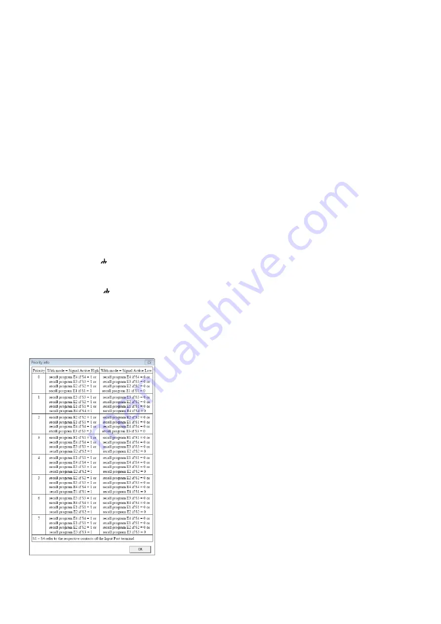
6.15.3 Selecting priorities
Under “Priority”, select the priority to be used
for the switching inputs during switchover .
Click the button “?” to call up a table (fig . 39)
providing information on the actual meaning
of the number entered in the field “Configure
Priority” . For each number, the table lists, in
descending order, the priorities that are as-
signed to the individual inputs .
Example:
All inputs have been enabled for switchover . The
logic type is “active High” and the value in the field
“Configure Priority” has been set to 3, i . e ., according
to the table, the order of the inputs is S1, S4, S3,
S2 . This means:
If switching input 1 is on high level (+5 V are present
between terminal “S1” and ), the 1
st
extra con-
figuration will be retrieved (consequently, the other
inputs will be of no relevance) .
If switching input 1 is on low level (0 V are present
between terminal “S1” and ) and if switching
input 4 is on high level, the 4
th
extra configuration
will be retrieved .
If the switching inputs 1 and 4 are on low level and
if switching input 3 is on high level, the 3
rd
extra
configuration will be retrieved .
If switching inputs 1, 3 and 4 are on low level and
if switching input 2 is on high level, the 2
nd
extra
configuration will be retrieved .
Fig. 39 Window “Priority Info”
6.16 Selecting the interface mode
Similar to the procedure in the system menu,
it is possible to define if one of the interfaces
USB or RS-485 is to be set manually or to be
recognized automatically by the unit .
1) In the configuration window, under
“USB/ RS 485”, click the button “Setup” .
The dialog window “USB/ RS 485 Setup”
is displayed .
2) From the list field, define if the switchover
is to be performed automatically (“USB/
RS 485 Automatic”) or if the USB or RS-
485 interface most recently set by means
of the system menu (
☞
chapter 5 .3 .3) is
to be used (“USB/ RS 485 Manual”) .
3) Click “OK” to confirm your selection or
click “Cancel” to cancel it .
6.17 Locking the unit
To protect the unit against unauthorized op-
eration, click the button “Lock Front-panel”
on the upper right of the display so that it
appears to be “pressed” . Once the connec-
tion to the computer has been disconnected
(configuration window closed [
☞
chap-
ter 6 .18] and “Disconnect” clicked), it will
not be possible to operate the DRM-882LAN
via its buttons
To unlock, re-establish the connection to
the computer (“Connect”), call up the con-
figuration window (“Edit”) and press (“disen-
gage”) the button “Lock Front-panel” .
6.18 Exiting a configuration window
To exit a configuration window, click the but-
ton
located in the upper right corner . Then
confirm the confirmation message .
7 Specifications
DRM-882LAN
Frequency range: . . . . .20 – 20 000 Hz
±1 dB
Audio inputs
Input voltage: . . . . . . .6 .2 V (max .)
Impedance: . . . . . . . .10 kΩ
Connections: . . . . . . .Screw terminals,
balanced
Phantom
power supply: . . . . . . .+48 V, switchable
Audio outputs
Output voltage: . . . . .6 .2 V (max .)
Impedance: . . . . . . . .50 Ω
Connections: . . . . . . .Screw terminals,
balanced
S/ N ratio (A-weighted)
Microphone: . . . . . . . .> 98 dB
Line: . . . . . . . . . . . . . .> 104 dB
THD: . . . . . . . . . . . . . . .< 0 .005 %
A / D and D /A converters
Quantization: . . . . . . .24 bit
Sampling rate: . . . . . .48 kHz
Signal processor
DSP type: . . . . . . . . . .SAM3716
Data format: . . . . . . . .24 bit (data)
× 96 bit (coeffi-
cients)
Switching inputs: . . . . .0 – 5 V (TTL level)
Switching outputs: . . . .0 – 5 V (TTL level),
150 mA (max .)
Power supply: . . . . . . . .230 V/ 50 Hz
Power consumption: . . .20 VA (max .)
Ambient temperature: .0 – 40 °C
Dimensions
Width: . . . . . . . . . . . .482 mm
Height: . . . . . . . . . . . .44 mm,
1 RS (rack space)
Depth: . . . . . . . . . . . .250 mm
Weight: . . . . . . . . . . . .2 .5 kg
DRM-882WP
Dimensions (W × H): . . .86 × 86 mm
Mounting depth: . . . .30 mm
Power supply: . . . . . . . .
⎓
5 V/ 20 mA
DRM-882WPX
Dimensions (W × H): . . .144 × 80 mm
Mounting depth: . . . .45 mm
Power supply: . . . . . . . .
⎓
12 V/ 75 mA
Subject to technical modification .
All rights reserved by MONACOR
®
INTERNATIONAL GmbH & Co. KG.
No part of this instruction manual may be reproduced in any form or by any means for any commercial use.


