Monacor 17.0014 Скачать руководство пользователя страница 35

35

English

6.6  Automixer

Sometimes multiple microphones are re-
quired, but only one is used at a time, e . g . 
in discussions . Due to the large number of 
open microphone channels, there will be a 
high level of background noise . This noise can 
be quite annoying . The noise gate (

 chap-

ter 6 .4 .6) can be used to suppress low-level 
noise from each microphone channel . For this, 
however, the noise gate of each channel must 
be accurately adjusted .

The function “Auto Mixer” is an addi-

tional option . Once you speak into one of 
the microphones involved, this microphone 
will be temporarily the master microphone . 
The levels of all other microphones will be 
attenuated .
To activate the automixer function, go to 
the view “Overview” (fig . 18) and tick the 
box “Active” under “Auto Mixer” . To set 
the parameters, click “Edit parameter” . The 
automixer window (fig . 29) is shown . There, 
the operating mode of the automixer can be 
selected:
With the operating mode “

N. O. M.

”, the at-

tenuation of the input channels will depend 
on the number of open microphones . The 
attenuation range is between 3 dB (two open 
microphones) and 9 dB (eight open micro-
phones) .
With the operating mode “

Gain Sharing

”, 

the total gain of all input channels will be kept 
at a constant value . The highest gain will be 
assigned to the channels with the highest 
signal level; the gain of the other channels will 
be reduced accordingly . The gain is calculated 
in a way that makes sure that the volume 
of the signal sum is such as if only a single 
microphone channel is open .
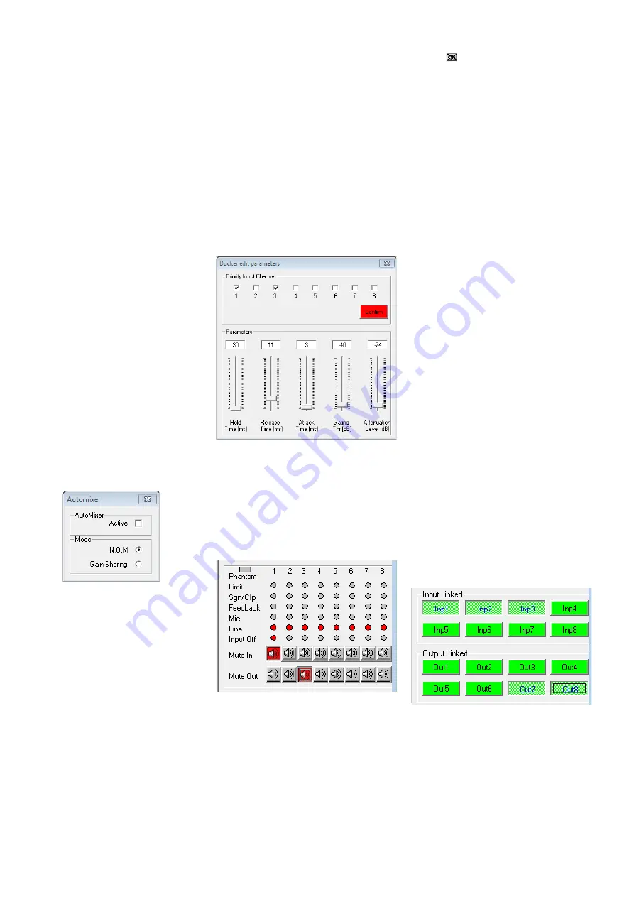
Fig. 29  Automixer

6.7  Ducker

Another option to improve speech intelligi-
bility is to give specific channels priority over 
other channels . Thus, background music can 
be automatically suppressed while announce-
ments are being made .

To select the priority channels, go to the 

view “Overview” (fig . 18) and tick the appro-
priate boxes “Priority Input Channel” under 
“Ducker” . Then click “Confirm” to confirm 
your selection .

To edit the parameters, click “Edit param- 

eter” . The ducker window (fig . 30) will be 
shown . There, the following parameters can 
be set:

–  Gating Thr: threshold value for the signal 

level of the priority input channels; when 
the level is exceeded, the other input sig-
nals will be attenuated

–  Attack Time: attack time
–  Hold Time: time for which the signals of 

the non-priority input channels will remain 
attenuated after the signals of the prior-
ity input channels have fallen below the 
threshold value “Gating Thr”

–  Release Time: time after which the atten-

uation of the signals of the non-priority 
channels will be deactivated after the “Hold 
Time” has elapsed

–  Attenuation Level: attenuation level
When all settings have been made, click 


in the upper right corner to exit the window .

Fig. 30  Ducker

6.8  Status display

Regardless of the view selected, the indica-
tors and controls on the right-hand side of 
the window are always available . They show 
the status and adjustments of the channels 
(fig . 31) just like the status LEDs (4) on the 
unit (

 chapter 5 .4) .

Fig. 31  Status display and muting

6.9  Muting

Use the buttons “Mute In” to mute the in-
puts, and use the buttons “Mute Out” to 
mute the outputs (fig . 31) . To mute or unmute 
a channel, click the appropriate button of the 

respective channel . When a channel is muted, 
the corresponding button appears in red and 
the icon   is shown in the view “Overview” 
(fig . 18) for this channel .

6.10 Linking channels

If specific parameters for multiple outputs or 
inputs are to be simultaneously adjusted to 
the same values, the inputs or outputs may 
be linked while the adjustments are being 
made . Thus, the parameters changed for one 
output will be adjusted accordingly for all 
outputs linked . Likewise, any changes made 
to one input will apply to all input channels 
linked . Only the parameters changed while 
the linkage was active are adopted by the 
other channels . All individual adjustments of 
the inputs or outputs are maintained .
To link input channels:
1)  On the right-hand side of the window, 

under “Input Linked” (fig . 32), click the 
buttons of all the inputs whose parameters 
are to be adjusted to the same value . The 
buttons appear to be “pressed” and the 
colour of their marking changes to blue .
These buttons are also available in the win-
dow “Inputs EQ” for input equalization 
(fig . 24) .

2)  To remove the link for an input, click the 

button of this input again .

To link output channels:
1)  On the right-hand side of the window, 

under “Output Linked” (fig . 32), click the 
buttons of all the outputs whose parame-
ters are to be adjusted to the same value . 
If a view for a specific output (fig . 27) is 
being displayed, click the button for this 
output as well . The buttons appear to be 
“pressed” and the colour of their marking 
changes to blue .
The linkage will be maintained even when 
another view is selected .

2)  To remove the link for an output, click the 

button of this output again .

Fig. 32  Linkage of inputs and outputs

Linking will have no effect on the following 
functions: “Mute In“, “Mute Out”, and the 
channel assignments “Output Routing” and 
“Output mix level” or “Balanced” (input sig-
nal) .

Содержание 17.0014

Страница 1: ...FOR SPECIALISTS ELECTRONICS FOR SPECIALISTS BEDIENUNGSANLEITUNG INSTRUCTION MANUAL Digitaler Matrix Router Digital Matrix Router DRM 882LAN Bestellnummer Order Number 17 9250 DRM 882WP Bestellnummer...

Страница 2: ...S2 S1 LINE OUTPUTS MIC LINE INPUTS CH4 CH8 CH7 CH6 CH5 CH8 CH7 CH6 CH5 CH3 CH2 CH1 CH4 CH3 CH2 CH1 FUSE 6 9 10 7 8 11 12 13 14 15 PRESET 3 PRESET 1 PRESET 2 UP DOWN PRESET 4 UNLOCKED 16 17 18 19 ESC...

Страница 3: ...ELECTRONICS FOR SPECIALISTS ELECTRONICS FOR SPECIALISTS ELECTRONICS FOR SPECIALISTS ELECTRONICS FOR SPECIALISTS 3 Deutsch Seite 4 English Page 22...

Страница 4: ...den Anschluss eines Computers zur Fernsteuerung und zum Konfigurieren des DRM 882LAN 1 2 R ckseite 6 Netzschalter POWER 7 Netzbuchse zum Anschluss an eine Steck dose 230V 50Hz ber das beiliegende Net...

Страница 5: ...ungssituationen Dabei k nnen vielf ltige DSP Funktionen wie Equalizer Noise Gates Delays R ck kopplungsunterdr ckung Kompressoren und Limiter genutzt werden Zur Verbesserung der Sprachverst ndlichkeit...

Страница 6: ...los lassen 4 Die Taste PRESET 3 16 dr cken bis die LED neben der Taste leuchtet alternativ PRESET 3 und PRESET 4 dr cken 5 Die Bedieneinheit von der Stromversor gung trennen und erneut verbinden 4 6 B...

Страница 7: ...en und deren Name im Display 2 angezeigt Nach dem Gebrauch zuerst die an den Ausg ngen angeschlossenen Ger te dann den DRM 882LAN mit dem Schalter POWER wieder ausschalten 5 2 Konfiguration w hlen Dur...

Страница 8: ...gt jetzt z B ID 01 4 Mit den Tasten PRESET 2 und PRESET 3 die gew nschte Ger tenummer 1 64 w hlen 5 Mit der Taste PRESET 1 das Untermen verlassen oder die Taste PRESET 4 dr cken um das Untermen ohne e...

Страница 9: ...bei der Einrichtung gew hlten Betriebsart Kapitel 4 6 1 Die Bedienung erfolgt ber die Tasten SET 24 ESC 25 und den Drehknopf 23 1 Mit dem Drehknopf einen Men punkt ausw hlen 2 Mit der Taste SET einen...

Страница 10: ...n Kopfzeile Informationen zur Schnittstelle und der Ver bindungsstatus angezeigt werden 6 2 1 Ger te hinzuf gen Um ein weiteres Ger t hinzuzuf gen auf die Schaltfl che Add Device klicken Ist USB als a...

Страница 11: ...Ethernet z B System Lock IP 192 168 001 101 und kann nicht mehr direkt bedient werden solange die Verbindung besteht Zum Trennen der Datenverbindung auf die Schaltfl che Disconnect im Fenster des ge w...

Страница 12: ...ss eine IP Adresse festlegen Eine Netzmaske wird automa tisch generiert Kapitel 5 3 1 Soll die Vergabe der IP Adresse automatisch durch einen im Netzwerk vorhandenen DHCP Server erfolgen hinter dhcp e...

Страница 13: ...ng Durch das Setzen des Hakens bei Phantom wird auf alle Eing nge die als Mikrofon Ein g nge konfiguriert sind Kapitel 6 4 1 eine 48 V Phantomspannung gelegt Einige Mikrofone ben tigen diese Phantomsp...

Страница 14: ...p w hlen Hochpass High Pass oder Tiefpass Low Pass Mit der Einstellung Bypass ist das Filter deaktiviert 2 Im Feld darunter die Grenzfrequenz ein stellen Abb 23 Eingangsfilter Wurde f r einen Eingang...

Страница 15: ...iken stehen zur Auswahl Buttw 6dB Butterworth Filter erster Ordnung mit einer Flankensteilheit von 6dB Oktave Buttw 12dB Butterworth Filter zweiter Ordnung mit einer Flankensteilheit von 12dB Oktave L...

Страница 16: ...hltem Regler auf der Tastatur mit den Pfeiltasten oder Bildlauf tasten Zum schnellen Zur ckstellen auf 0dB die Schaltfl che 0dB unterhalb des Reglers anklicken Soll die Verst rkung nur vor bergehend...

Страница 17: ...er bevorzugten Kan le den Schwellwert Gating Thr wie der unterschritten haben Release Time R ckstellzeit in der die Sig nale der nicht bevorzugten Kan le wieder eingeblendet werden nachdem die Hold Ti...

Страница 18: ...Schaltsignale an den Eing ngen INPUT PORT 13 aufrufen Kapitel 6 15 Alle Konfigurationen lassen sich zus tzlich auf dem Computer speichern 6 13 1 Konfiguration auf dem Computer speichern Zum Speichern...

Страница 19: ...ew nschten Schaltausg nge in den entsprechenden Eingabefeldern berschreiben max 16 Zeichen 3 Die Eingaben mit Confirm best tigen oder den Vorgang mit Cancel abbre chen Die eingegebenen Namen werden au...

Страница 20: ...Konfigurationsfenster unter USB RS 485 auf die Schaltfl che Setup klicken Das Dialogfenster USB RS485 Setup wird eingeblendet 2 Im Listenfeld w hlen ob eine automatische Umschaltung erfolgen soll USB...

Страница 21: ...21...

Страница 22: ...ect a computer for remote controlled operation of the DRM 882LAN via Ethernet the two LEDs above the jack indicate that the connection is being established or that data is being transferred 10RJ45 jac...

Страница 23: ...equal izers noise gates delays feedback suppres sion compressors and limiters are available A ducking function and an automixer function are provided to improve speech intelligibility In the control o...

Страница 24: ...n lights up as an alternative press buttons PRESET 3 and PRESET 4 5 Disconnect the control panel from the power supply and then connect it again 4 6 Control panel DRM 882WPX The control panel DRM 882W...

Страница 25: ...n on the display then the con figuration that was used when the unit was switched off is loaded and its name appears on the display 2 After usage first switch off the units con nected to the outputs a...

Страница 26: ...the submenu The display shows for example the following ID 01 4 Use the buttons PRESET 2 and PRESET 3 to select the unit ID desired 1 64 5 Use the button PRESET 1 to exit the sub menu or the button PR...

Страница 27: ...r operation the buttons SET 24 and ESC 25 and the rotary knob 23 are used 1 Use the rotary knob to select a menu item 2 Use the button SET to call up a menu item or to execute a function 3 Use the rot...

Страница 28: ...nnected to a control panel DRM 882WP 882WPX make sure that the control panel is not operated while the DRM 882LAN is remote controlled via a computer e g lock the control panel Otherwise connection co...

Страница 29: ...onnection or System Lock Online Device ID 01 or if controlled via Ethernet System Lock IP 192 168 001 101 The unit cannot be directly operated as long as the connection exists To disconnect the data c...

Страница 30: ...5 3 1 or 5 3 4 or as described in the following via the computer Connect the units one after another to the PC using the USB interface and make the following settings for each unit 1 If the USB interf...

Страница 31: ...ap ter 6 4 1 with a phantom power of 48V Some microphones require this phantom power supply for operation CAUTION Signal sources with unbal anced signal outputs may be damaged by the phantom power sup...

Страница 32: ...el depending on the equal ization adjustment In the upper right of the diagram the type of representation can be selected mag nitude frequency response Mag or phase frequency response Phase Click the...

Страница 33: ...ith a slope of 12dB octave Bessel 12dB Bessel filter of second order with a slope of 12dB octave Buttw 18dB Butterworth filter of third order with a slope of 18dB octave Buttw 24dB Butterworth filter...

Страница 34: ...Up or Pg Down keys on the keyboard To quickly reset the gain to 0dB click the button 0 dB beneath the slider To temporarily adjust the gain to 0dB click the button Bypass Level the button will appear...

Страница 35: ...value Gating Thr Release Time time after which the atten uation of the signals of the non priority channels will be deactivated after the Hold Time has elapsed Attenuation Level attenuation level When...

Страница 36: ...PORT 13 chapter 6 15 All configurations may be additionally saved on the computer 6 13 1 Saving configurations on the computer To save the current configuration on the com puter 1 On the upper right...

Страница 37: ...utputs 1 Click the button Edit Switch Name The dialog window Edit Switch Name is dis played fig 37 2 Overwrite the names of the desired switch ing outputs in the corresponding input fields max 16 char...

Страница 38: ...y the unit 1 In the configuration window under USB RS 485 click the button Setup The dialog window USB RS 485 Setup is displayed 2 From the list field define if the switchover is to be performed autom...

Страница 39: ...39...

Страница 40: ...MONACOR INTERNATIONAL GmbH Co KG Zum Falsch 36 28307 Bremen Germany Copyright by MONACOR INTERNATIONAL All rights reserved A 2016 99 02 01 2020...

Отзывы: