


32
English
6.4.7 Sound adjustment
Each input provides a basic filter (Filter 1st
order) and an equalizer (EQ) offering a wide
range of sound adjustment options . For mi-
crophone inputs, equalization is only available
as an alternative to feedback suppression .
To set the basic filter:
1) In the list field, under “Filter 1st order”
(fig . 23), select the filter type: “High Pass”
or “Low Pass” .
To deactivate the filter, select “Bypass” .
2) Set the cut-off frequency in the field under
the list field .
Fig. 23 Input filter
If the signal level “Mic” was selected for an
input, the option “EQ” must be selected
under “Sel Fbk / EQ” so that the equalization
function can be used .
To adjust the equalization, click the but-
ton “Edit” under “EQ” . The window “Inputs
EQ” (fig . 24) is displayed, indicating the sound
adjustments for the input selected . Use the
tabs in the upper section of the window to
select other inputs .
Under “EQ”, the 3 independent filters of the
input channel can be adjusted (fig . 25) . The
following filter types are available:
Peaking_Eq / PEAK EQ (Peaking Equalizer)
Filter with bell characteristic with adjusta-
ble gain /attenuation (dB), center frequency
(Hz) and quality factor (Q)
Hi-Shelv_Q / HiSHF Q (High Shelving Filter Q)
Symmetric high frequency filter with shelv-
ing characteristic
For the adjustable cut-off frequency (Hz),
the level is half of the gain /attenuation
adjusted (dB); the slope depends on the
adjustable quality factor (Q) .
Lo-Shelv_Q / LoSHF Q (Low Shelving Filter Q)
Symmetric low frequency filter with shelv-
ing characteristic
For the adjustable cut-off frequency (Hz),
the level is half of the gain /attenuation
adjusted (dB); the slope depends on the
adjustable quality factor (Q) .
1)
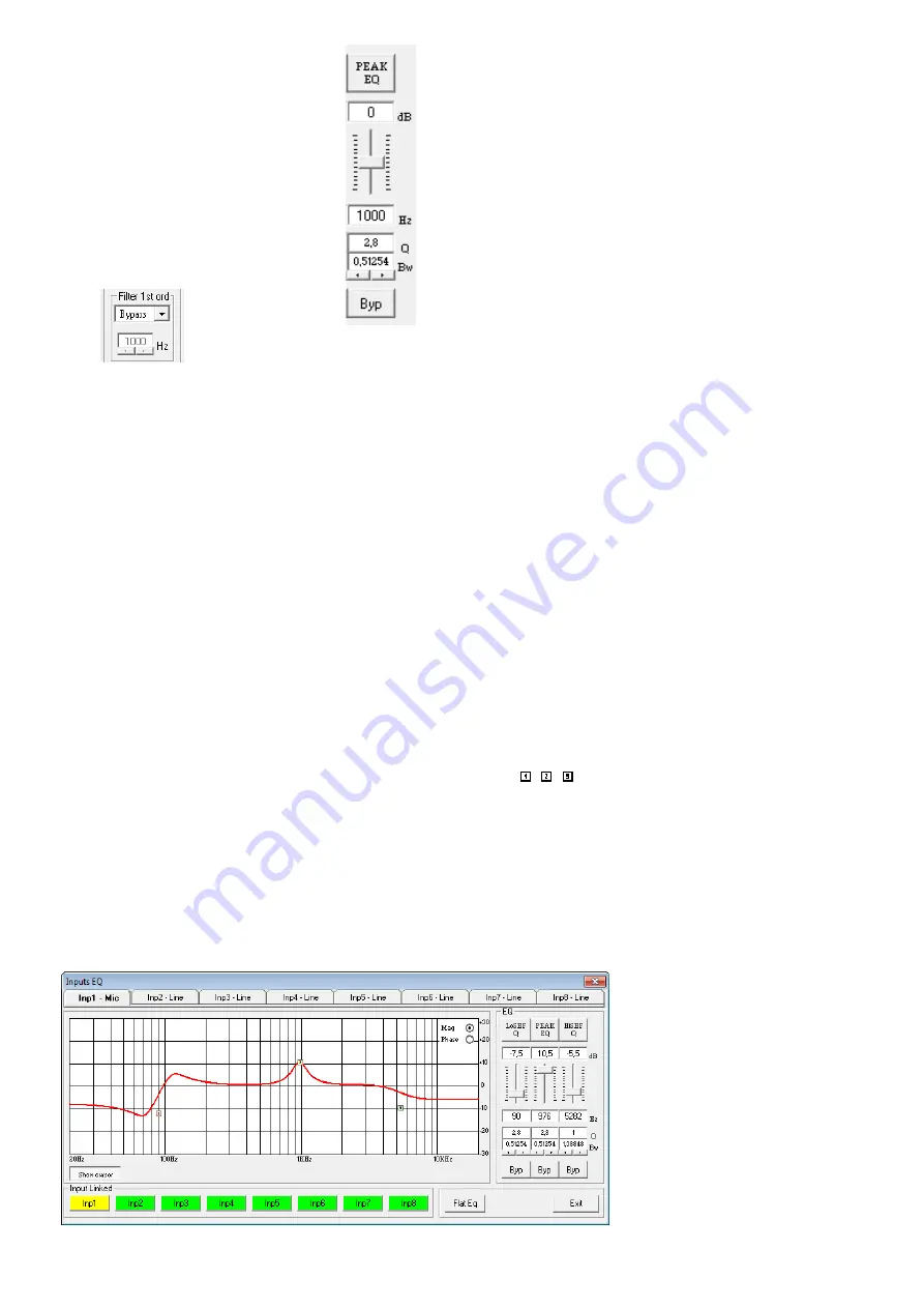
Fig. 25 “EQ”
Use the upper button (here,
“PEAK EQ”) to call up a dia-
log window, and then select
the filter type .
2) Use the slider to adjust the
level boosting or the level
attenuation .
3) In the field “Hz” beneath
the slider, enter the filter
frequency .
4) Enter the filter quality factor
(Q) or the relative bandwidth
value (Bw) in the correspond-
ing field or set them by click-
ing the arrows beneath the
fields . Numbers entered will
be rounded to the nearest
value possible .
5) To deactivate individual filters, click the
button “Byp” . The button will appear in
red . To activate the filter, click the button
again .
6) To reset the gain values (0 dB) of all filters
of the input, click the button “Flat Eq” .
In the dialog window “Flat Eq – Are you
sure?” that appears, confirm or cancel the
procedure .
7) Use the button “Exit” to exit the equali-
zation function .
Note:
Alternatively, the level boosting/attenuation
and the filter frequency can also be adjusted graph-
ically (
☞
6.4.7.1 Frequency response
The diagram indicates the frequency response
of the input channel, depending on the equal-
ization adjustment .
In the upper right of the diagram, the
type of representation can be selected: mag-
nitude frequency response (“Mag”) or phase
frequency response (“Phase”) .
Click the button “Show cursor” to show
a graphical reference point ( , , ) next
to the curve for each filter (fig . 24) . Use the
mouse to move the reference points and thus
to graphically adjust the frequency and the
level boosting / level attenuation of the filters .
Click the button “Show cursor” again to
hide the reference points .
Fig. 24 Window of the input equalization “Inputs EQ”
6.4.8 Feedback suppression
(FBK)
If the signal level “Mic” has been selected
for an input, the function “FBK” under “Sel
Fbk / EQ” may be used (fig . 19) instead of the
equalization function . The function “FBK” is
an effective algorithm based on a frequency
shift for feedback suppression that allows
users to adjust higher volumes for speech
applications without having any interfering
howling sounds .
Use the slider “Feedback dev freq [Hz]”
to adjust the level of the frequency shift: the
higher the value, the more effective the feed-
back suppression .
6.4.9 Phase reversal
The signal of the input can be reversed . This
may, for example, counteract phase cancel-
lations that occur when two microphones are
located in different directions to / distances
from the same sound source . A tick in the
box “Phase 180°” indicates that the signal
is reversed . Click the box to deactivate the
phase reversal function .
6.5 Configuring outputs
The signals of all outputs take the processing
path shown in figure 6 . The view “Routing”
is used to assign the input signals to the out-
puts; the other settings of the outputs, how-
ever, are defined in a separate view for each
output channel .
Outputs may be linked (
☞
so that multiple outputs can simultaneously
be set to the same values .
6.5.1 Assigning / Mixing input signals
1) To assign the desired input signals to each
output and to define their mixing ratio,
select the view “Routing” (fig . 26) .
2) Use the matrix “Output Routing” to select
the input signals that are to be assigned to
an output channel . Each row of the matrix
represents an input channel, and each col-
umn represents an output channel . Click a
node to assign an input to an output (the
square located at the node will appear in
red) or to remove the assignment .
3) Use the slider under “Editing mix routing”
to attenuate the level for each assigned
input signal by up to 30 dB (the attenua-
tion will only apply to this output channel) .
Thus, different signal mixing ratios for the
outputs can be defined . Clicking a node
in the matrix will automatically select the
control group of the corresponding out-
put; alternatively, the output may also be
selected by means of the buttons “Output
Selected” .
4) To remove all assignments, click the button
“Reset” and then confirm the confirma-
tion message .
Colour lines in the view “Overview” (
☞
fig . 18)
indicate the channel assignments .
Fig. 26 View “Routing”


