Monacor 17.0014 Скачать руководство пользователя страница 30

30

English

6.2.9  Changing the interface

To change to one of the other interface types 
supported, first remove all units from the 
main window (

 chapter 6 .2 .6) .

1)  Click the button on the upper left . De-

pending on the interface currently select-
ed, the text on the button is “USB-COMx”, 
“RS485-COMx” or “TCP/ IP” .
The following dialog window is displayed:

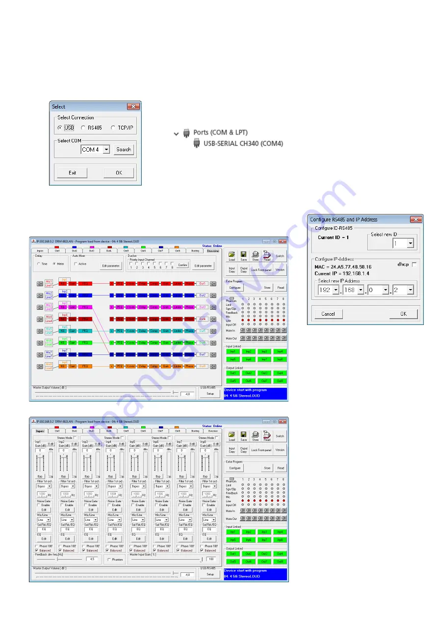
Fig. 17  Window “Select Connection” – USB

2)  Under “Select Connection”, select the 

interface desired (“USB”, “RS485” or 
“TCP/ IP”) .

3)  For “RS485”, the number of the port used 

for this interface must be selected under 
“Select COM” . For “USB” (fig . 19), the 
serial interface that simulates the driver 
for this software must be selected under 
“Select COM” . Check the settings of the 
operating system for the appropriate COM 
interface or use the button “Search” to 
have it determined automatically .
The corresponding settings of the oper-
ating system can be found under “Device 
Manager 

 Ports (COM & LPT) .

There, the following is shown (example):

If there are conflicts with other units, the 
number of the COM interface may be 
changed here .

Note:

 To avoid communication problems, it is rec-

ommended to manually change the COM numbers 
10 and higher that are automatically assigned by the 
computer to the COM numbers 1 to 9 .

6.2.10  Setting the ID number or 

the IP address

To operate  multiple DRM-882LAN by remote 
control via RS-485 or TCP/ IP, a separate ID 
number or IP address must be assigned to 
each unit prior to their first simultaneous op-
eration . This may be done in the system menu 
(

 chapter 5 .3 .1 or 5 .3 .4) or, as described in 

the following, via the computer .
Connect the units one after another to the 
PC, using the USB interface, and make the 
following settings for each unit:
1)  If the USB interface has not been selected, 

use the main window to go to the USB 
interface (

 chapter 6 .2 .9) .

2)  Add a unit (button “Add device”, 

 chap-

ter 6 .2 .1) .

3)  Connect the unit (button “Connect”, 

 chapter 6 .2 .3) .

4)  Click the button “ID & IP” that is now 

available . The following dialog window 
is displayed:

Fig. 20   Window “Configure ID-RS485 and 

IP Address”

5)  For remote control via RS-485, select an 

ID number (1– 64) under “Select new ID” . 

Note:

 If, after its configuration, a DRM-882LAN 

is not to be controlled via the computer but via 
the control panel DRM-882WP, make sure that 
the ID of the DRM-882LAN is set to 1 . If the 
DRM-882LAN is to be controlled via the control 
panel DRM-882WPX, its ID number can be set 
as desired .

For remote control via Ethernet, define 
an IP address under “Select new IP Ad-
dress” . A network mask will automatically 
be generated (

 chapter 5 .3 .1) . If the 

IP address is to be assigned automatically 
by a DHCP server in the network, tick the 
option “dhcp” (

 chapter 5 .3 .2) .

6)  Click “OK” to confirm or “Cancel” to 

cancel .

7)  Use the button “Disconnect” to discon-

nect the data connection and then con-
firm the confirmation message . If desired, 
connect another DRM-882LAN to the USB 
port of the computer and continue with 
step 3 .

Then go to the interface desired for controlling 
and configuring the units (

 chapter 6 .2 .9) .

6.2.11  Exiting the program

Use the button “Exit” or the icon 

 in the 

upper right corner to exit the program . Then 
confirm the confirmation message .

Fig. 18  View “Overview”

Fig. 19  View of the input channels “Inputs”

Содержание 17.0014

Страница 1: ...FOR SPECIALISTS ELECTRONICS FOR SPECIALISTS BEDIENUNGSANLEITUNG INSTRUCTION MANUAL Digitaler Matrix Router Digital Matrix Router DRM 882LAN Bestellnummer Order Number 17 9250 DRM 882WP Bestellnummer...

Страница 2: ...S2 S1 LINE OUTPUTS MIC LINE INPUTS CH4 CH8 CH7 CH6 CH5 CH8 CH7 CH6 CH5 CH3 CH2 CH1 CH4 CH3 CH2 CH1 FUSE 6 9 10 7 8 11 12 13 14 15 PRESET 3 PRESET 1 PRESET 2 UP DOWN PRESET 4 UNLOCKED 16 17 18 19 ESC...

Страница 3: ...ELECTRONICS FOR SPECIALISTS ELECTRONICS FOR SPECIALISTS ELECTRONICS FOR SPECIALISTS ELECTRONICS FOR SPECIALISTS 3 Deutsch Seite 4 English Page 22...

Страница 4: ...den Anschluss eines Computers zur Fernsteuerung und zum Konfigurieren des DRM 882LAN 1 2 R ckseite 6 Netzschalter POWER 7 Netzbuchse zum Anschluss an eine Steck dose 230V 50Hz ber das beiliegende Net...

Страница 5: ...ungssituationen Dabei k nnen vielf ltige DSP Funktionen wie Equalizer Noise Gates Delays R ck kopplungsunterdr ckung Kompressoren und Limiter genutzt werden Zur Verbesserung der Sprachverst ndlichkeit...

Страница 6: ...los lassen 4 Die Taste PRESET 3 16 dr cken bis die LED neben der Taste leuchtet alternativ PRESET 3 und PRESET 4 dr cken 5 Die Bedieneinheit von der Stromversor gung trennen und erneut verbinden 4 6 B...

Страница 7: ...en und deren Name im Display 2 angezeigt Nach dem Gebrauch zuerst die an den Ausg ngen angeschlossenen Ger te dann den DRM 882LAN mit dem Schalter POWER wieder ausschalten 5 2 Konfiguration w hlen Dur...

Страница 8: ...gt jetzt z B ID 01 4 Mit den Tasten PRESET 2 und PRESET 3 die gew nschte Ger tenummer 1 64 w hlen 5 Mit der Taste PRESET 1 das Untermen verlassen oder die Taste PRESET 4 dr cken um das Untermen ohne e...

Страница 9: ...bei der Einrichtung gew hlten Betriebsart Kapitel 4 6 1 Die Bedienung erfolgt ber die Tasten SET 24 ESC 25 und den Drehknopf 23 1 Mit dem Drehknopf einen Men punkt ausw hlen 2 Mit der Taste SET einen...

Страница 10: ...n Kopfzeile Informationen zur Schnittstelle und der Ver bindungsstatus angezeigt werden 6 2 1 Ger te hinzuf gen Um ein weiteres Ger t hinzuzuf gen auf die Schaltfl che Add Device klicken Ist USB als a...

Страница 11: ...Ethernet z B System Lock IP 192 168 001 101 und kann nicht mehr direkt bedient werden solange die Verbindung besteht Zum Trennen der Datenverbindung auf die Schaltfl che Disconnect im Fenster des ge w...

Страница 12: ...ss eine IP Adresse festlegen Eine Netzmaske wird automa tisch generiert Kapitel 5 3 1 Soll die Vergabe der IP Adresse automatisch durch einen im Netzwerk vorhandenen DHCP Server erfolgen hinter dhcp e...

Страница 13: ...ng Durch das Setzen des Hakens bei Phantom wird auf alle Eing nge die als Mikrofon Ein g nge konfiguriert sind Kapitel 6 4 1 eine 48 V Phantomspannung gelegt Einige Mikrofone ben tigen diese Phantomsp...

Страница 14: ...p w hlen Hochpass High Pass oder Tiefpass Low Pass Mit der Einstellung Bypass ist das Filter deaktiviert 2 Im Feld darunter die Grenzfrequenz ein stellen Abb 23 Eingangsfilter Wurde f r einen Eingang...

Страница 15: ...iken stehen zur Auswahl Buttw 6dB Butterworth Filter erster Ordnung mit einer Flankensteilheit von 6dB Oktave Buttw 12dB Butterworth Filter zweiter Ordnung mit einer Flankensteilheit von 12dB Oktave L...

Страница 16: ...hltem Regler auf der Tastatur mit den Pfeiltasten oder Bildlauf tasten Zum schnellen Zur ckstellen auf 0dB die Schaltfl che 0dB unterhalb des Reglers anklicken Soll die Verst rkung nur vor bergehend...

Страница 17: ...er bevorzugten Kan le den Schwellwert Gating Thr wie der unterschritten haben Release Time R ckstellzeit in der die Sig nale der nicht bevorzugten Kan le wieder eingeblendet werden nachdem die Hold Ti...

Страница 18: ...Schaltsignale an den Eing ngen INPUT PORT 13 aufrufen Kapitel 6 15 Alle Konfigurationen lassen sich zus tzlich auf dem Computer speichern 6 13 1 Konfiguration auf dem Computer speichern Zum Speichern...

Страница 19: ...ew nschten Schaltausg nge in den entsprechenden Eingabefeldern berschreiben max 16 Zeichen 3 Die Eingaben mit Confirm best tigen oder den Vorgang mit Cancel abbre chen Die eingegebenen Namen werden au...

Страница 20: ...Konfigurationsfenster unter USB RS 485 auf die Schaltfl che Setup klicken Das Dialogfenster USB RS485 Setup wird eingeblendet 2 Im Listenfeld w hlen ob eine automatische Umschaltung erfolgen soll USB...

Страница 21: ...21...

Страница 22: ...ect a computer for remote controlled operation of the DRM 882LAN via Ethernet the two LEDs above the jack indicate that the connection is being established or that data is being transferred 10RJ45 jac...

Страница 23: ...equal izers noise gates delays feedback suppres sion compressors and limiters are available A ducking function and an automixer function are provided to improve speech intelligibility In the control o...

Страница 24: ...n lights up as an alternative press buttons PRESET 3 and PRESET 4 5 Disconnect the control panel from the power supply and then connect it again 4 6 Control panel DRM 882WPX The control panel DRM 882W...

Страница 25: ...n on the display then the con figuration that was used when the unit was switched off is loaded and its name appears on the display 2 After usage first switch off the units con nected to the outputs a...

Страница 26: ...the submenu The display shows for example the following ID 01 4 Use the buttons PRESET 2 and PRESET 3 to select the unit ID desired 1 64 5 Use the button PRESET 1 to exit the sub menu or the button PR...

Страница 27: ...r operation the buttons SET 24 and ESC 25 and the rotary knob 23 are used 1 Use the rotary knob to select a menu item 2 Use the button SET to call up a menu item or to execute a function 3 Use the rot...

Страница 28: ...nnected to a control panel DRM 882WP 882WPX make sure that the control panel is not operated while the DRM 882LAN is remote controlled via a computer e g lock the control panel Otherwise connection co...

Страница 29: ...onnection or System Lock Online Device ID 01 or if controlled via Ethernet System Lock IP 192 168 001 101 The unit cannot be directly operated as long as the connection exists To disconnect the data c...

Страница 30: ...5 3 1 or 5 3 4 or as described in the following via the computer Connect the units one after another to the PC using the USB interface and make the following settings for each unit 1 If the USB interf...

Страница 31: ...ap ter 6 4 1 with a phantom power of 48V Some microphones require this phantom power supply for operation CAUTION Signal sources with unbal anced signal outputs may be damaged by the phantom power sup...

Страница 32: ...el depending on the equal ization adjustment In the upper right of the diagram the type of representation can be selected mag nitude frequency response Mag or phase frequency response Phase Click the...

Страница 33: ...ith a slope of 12dB octave Bessel 12dB Bessel filter of second order with a slope of 12dB octave Buttw 18dB Butterworth filter of third order with a slope of 18dB octave Buttw 24dB Butterworth filter...

Страница 34: ...Up or Pg Down keys on the keyboard To quickly reset the gain to 0dB click the button 0 dB beneath the slider To temporarily adjust the gain to 0dB click the button Bypass Level the button will appear...

Страница 35: ...value Gating Thr Release Time time after which the atten uation of the signals of the non priority channels will be deactivated after the Hold Time has elapsed Attenuation Level attenuation level When...

Страница 36: ...PORT 13 chapter 6 15 All configurations may be additionally saved on the computer 6 13 1 Saving configurations on the computer To save the current configuration on the com puter 1 On the upper right...

Страница 37: ...utputs 1 Click the button Edit Switch Name The dialog window Edit Switch Name is dis played fig 37 2 Overwrite the names of the desired switch ing outputs in the corresponding input fields max 16 char...

Страница 38: ...y the unit 1 In the configuration window under USB RS 485 click the button Setup The dialog window USB RS 485 Setup is displayed 2 From the list field define if the switchover is to be performed autom...

Страница 39: ...39...

Страница 40: ...MONACOR INTERNATIONAL GmbH Co KG Zum Falsch 36 28307 Bremen Germany Copyright by MONACOR INTERNATIONAL All rights reserved A 2016 99 02 01 2020...

Отзывы: