Section 4 - Overview
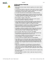
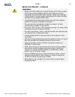
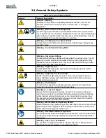
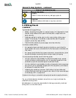
WARNING
Ensure that you have fully read “Section 3 - Safety” before setting up or
operating the E-Drive controller.
4.1
Specification
The following are general specifications. The supplied E-Drive may have
contractual variations and differ in some options.
4.1.1 Cabinet
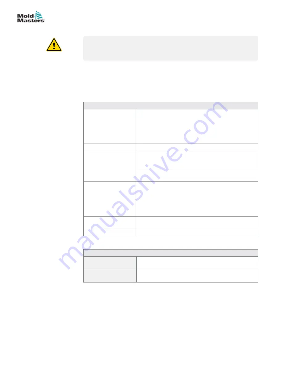
Table 4-1 Cabinet Information
Supply Voltage and
Current Rating
380-480vac, 50/60 Hz, 3 phase delta (Neutral not
required), Maximum of 20A per phase.
Refer to the serial plate on the controller cabinet for
confirmation of the supply requirements for your model.
If the local supply is outside the specified range please
contact
Mold-Masters
office for advice.
Voltage Bandwidth
Stable within
±
20% supply voltage swing
Over Current Unit
Protection
Rear-mounted Miniature Circuit Breaker gives over
current protection and may also be used as a lockable
main isolator
Input from Associated
Controller
A HAN4A connector accepts an “Up to heat” signal which
is required before the E-Drive is operable
I/O Connection and
Alarm Channel
HAN10E has the following functions
“E-Drive ready” output
Accepts incoming trigger(s) to operate E-Drive from a dry
contact or an external 24V source.
Isolated closing contact to give a common alarm output
signal
Servo Output Cables
Non-detachable cables provided as one pair per servo
drive
Cabinet Size (in mm)
448 (D) x 350 (W) x 500 (H)
4.1.2 Pendant
Table 4-2 Pendant Information
Emergency Shutdown
Button
Latching push-to-operate and turn-to-release button.
Hot Runner Controller
Interface
LCD Touch Screen for HMI
4.2 Future Expansion
The E-drive unit has been designed to give years of service and has the
ability to receive firmware updates, to allow newly developed features to be
easily added as they become available.
4-1
OVERVIEW
E-Drive Controller User Manual (with Pendant HMI)
© 2020 Mold-Masters (2007) Limited. All Rights Reserved.
Содержание E-Drive Series
Страница 1: ...version 3 User Manual with Pendant HMI Original Instructions ...
Страница 2: ......
Страница 26: ......
Страница 36: ......


