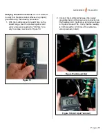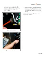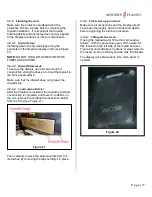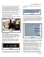
P a g e | 8
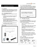
3.2.2.1
Product Drawing
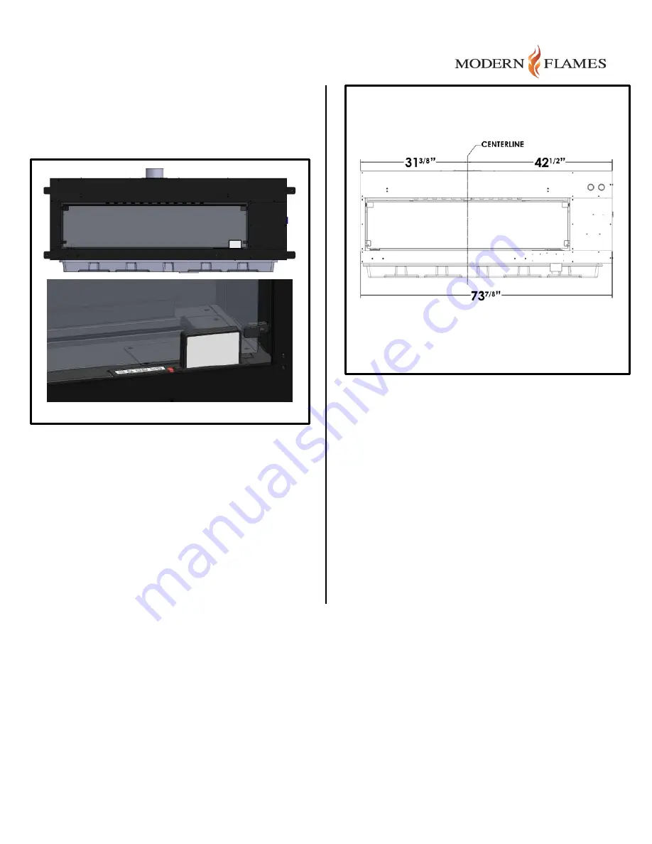
Refer to the detailed product drawing in Figure 5. A
front view of the assembly is shown along with a
detail of the front panel settings pad and display
assembly.
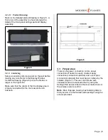
3.2.3
Centering
Setup a centerline reference point on the wall before
making any cuts. Refer to the Display Window
Centerline drawing (Figure 6) since the firebox is
larger on the right side.
Make sure that the center of the fire display area is
properly located within the room as planned in
advance.
3.3
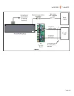
Preparation
There is one power connection (or two power
connections if heater is used), a water supply
connection (connection optional), and a vent pipe
(connection optional) that must be put in place by the
installer (Figure 7). The user controls are self-
contained and are accessed either by using the
Settings Pad as described in the User Instructions or
the wireless remote control.
Note:
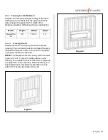
Main fireplace housing has fastening tabs to
firmly secure it to the framed wall openings using the
screws provided.
Figure 5
Figure 6
Содержание FusionFire 60
Страница 9: ...P a g e 9 Figure 7 ...


