P a g e | 11
3.3.2
Electrical Power Connections
Small wall plug-in convertor power sources must
NOT be used to power the fireplace because of this
fireplace’s higher power requirements. Even under
the best of conditions, it is only possible to power the
system using a dedicated line back to the breaker
box; do not connect to other equipment or outlets
located in the room.
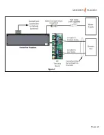
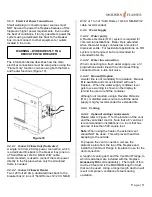
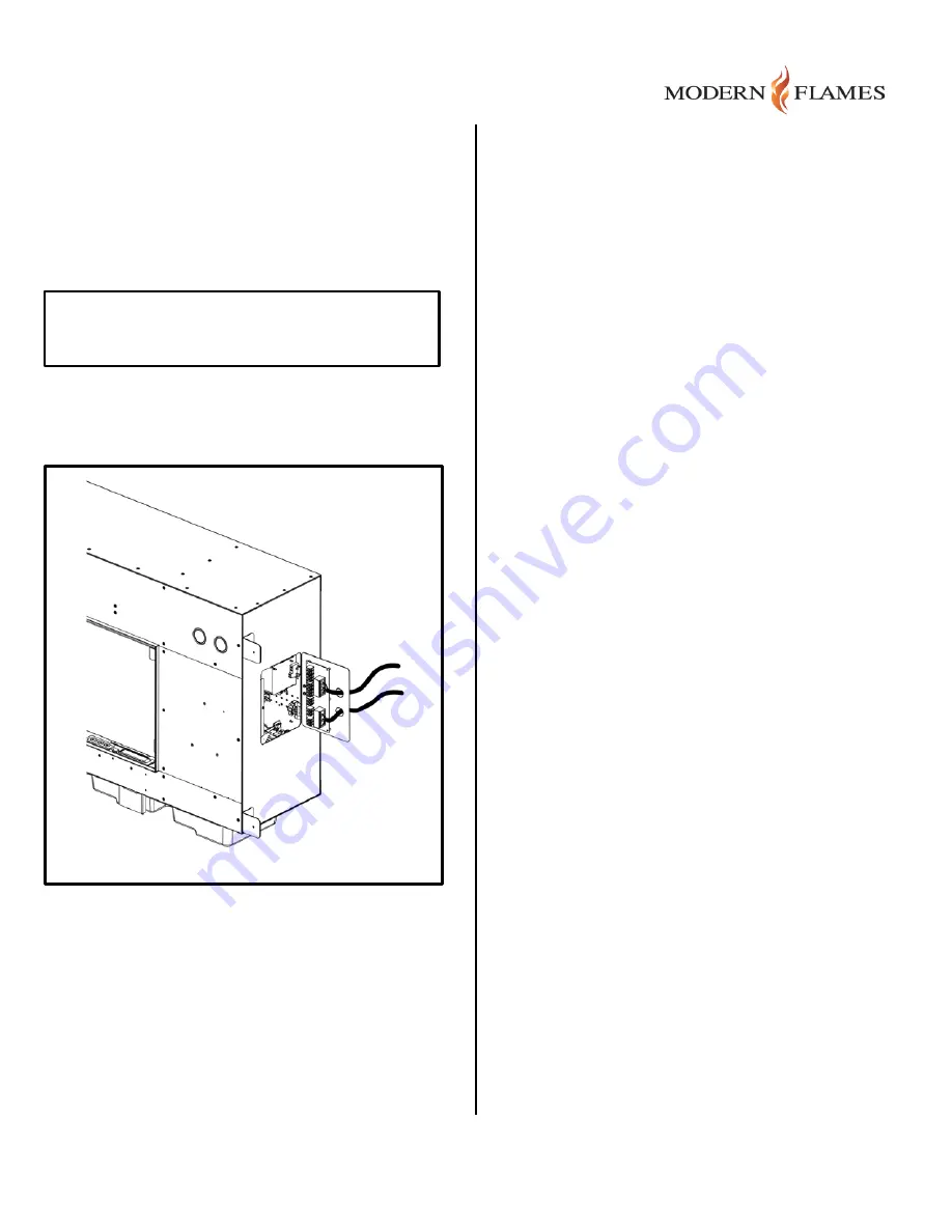
The information below describes how the main
electrical connections must be setup when using the
“Flame Only” function or when using both the flame
and heater functions (Figure 10).
3.3.2.1
Connect: Flame Only (No Heater)
A single 120 Volt, 20 Amp power connection, which
is a dedicated line back to the breaker box (one run
of “Solid Romex 12/2 CU NM-B W/G” cable
recommended), is used to connect the main power
directly to the fireplace when only the simulated
flame is needed.
3.3.2.2
Connect: Flame & Heater
Two 120 Volt 20 Amp, dedicated lines back to the
breaker box (2 runs of “Solid Romex 12/2 CU NM-B
W/G” or 1 run of “Solid Romex 12/4 CU NM-B W/G”
cable recommended).
3.3.3
Water Supply
3.3.3.1
Water purity
A Reverse Osmosis (R.O.) system is required for
commercial installations. Boiler life is extended
when the water supply contains low amounts of
dissolved solids. For residential applications, an RO
system is not required, but recommended for
extended boiler life.
3.3.3.2
Water line connection
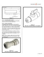
When connecting to a fresh water supply, use a ¼”
polyurethane water line with a John Guest fitting
connected to an in-line ball valve.
3.3.3.3
Manual fill option
A water line is not mandatory for operation. Manual
fill is available and comes standard with each
fireplace. When the water supply container level
gets low, a warning is shown on the display to
remind the user to refill the container.
Although not required, using a Reverse Osmosis
(R.O.) or distilled water source to refill the water
supply is highly recommended for extended life.
3.3.4
Venting
3.3.4.1
Optional venting requirements
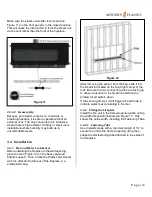
Please refer to Figure 11 for the location of the vent
and the vent slider control. Note that a 6” vent duct
is recommended in installations in a room that has
an area of less than 500 square feet.
Note:
When using the heater, the external vent
should NOT be used. This will prevent heat from
escaping to the outside.
To prepare the vent connection, remove the
protective plate from the top of the fireplace and
install the Vent Duct Flange in its place to use for the
duct connection.
A length of venting duct and the Vent Duct Flange, to
which is attached, are included with the fireplace
Accessory Kit
(sold separately). The length of this
duct is 20 feet and is the MAXIMUM length of duct
that can be used. Using a longer length duct run will
result in improper ventilation of steam during
operation.
WARNING – WIRE DIRECTLY TO A
DEDICATED 20A BREAKER
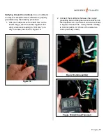
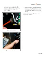
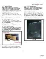
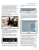
Figure 10
Содержание FusionFire 60
Страница 9: ...P a g e 9 Figure 7 ...


