


Chapter Five: Maintenance and Troubleshooting
Preventive Maintenance
38
3.
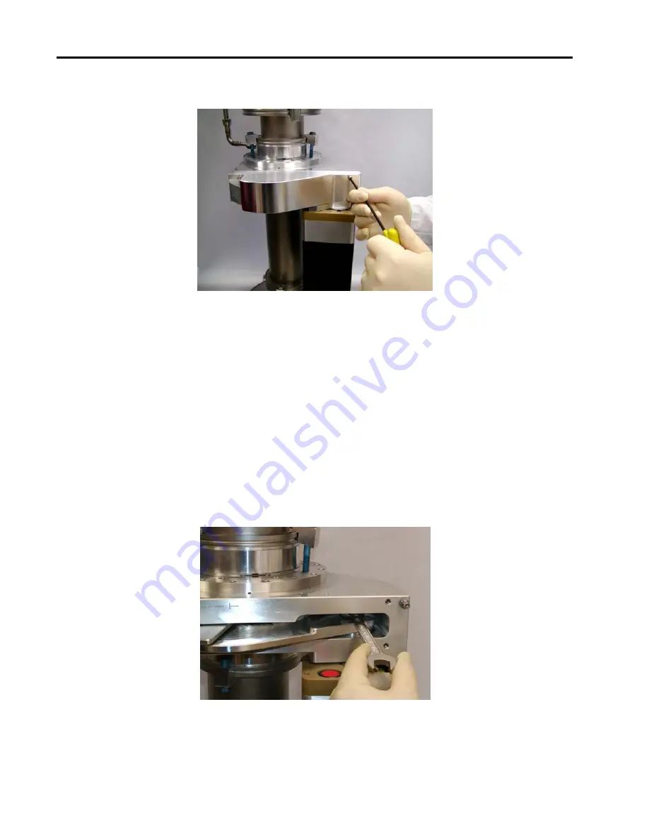
Loosen the valve cover screws (4) and remove the cover. Refer to Figure 16.
Figure 16: Four (4) Valve Cover Screws
4.
Select the
Pendulum Maintenance Mode Screen
on the tool computer.
5.
At the
Pendulum Maintenance Mode Screen,
select the “
Select Position Control Mode
” command.
6.
At the
Pendulum Maintenance Mode Screen,
select the “
Move Gate to 50 Percent Position
” command.
(This will move the gate to the 50% position and allow access to the bolt(s) holding in the gate.)
7.
Observe the bolt(s) attaching the gate to the main shaft. If there is only one bolt, skip to Step 8.
Otherwise, loosen the outer bolt with a ½” open end wrench. The outer bolt is the bolt located farthest
from the centerline of the valve bore.
8.
At the
Pendulum Maintenance Mode Screen
, select the “
Move Gate to 100 Percent Position
” command.
(This will move the gate to the 100%, full open, position and allow access to the bolt(s) holding in the
gate.)
9.
Loosen the remaining bolt attaching the gate to the main shaft (using a ½” open end wrench). Refer to
Figure 17.
Figure 17: Gate Bolt
10.
Remove the gate.
Содержание T3PIA
Страница 3: ...MKS Type T3PIA Pendulum Valve With Analog TTL Interface...
Страница 8: ...viii This page intentionally left blank...
Страница 27: ...Electrical Information Chapter Two Installation 19 Figure 4 Top Panel of the T3P Unit...
Страница 32: ...Chapter Two Installation Startup 24 This page intentionally left blank...
Страница 60: ...Appendix C Dimensions 52...
Страница 61: ...Appendix C Dimensions 53...
Страница 62: ...Appendix C Dimensions 54...
Страница 63: ...Appendix C Dimensions 55...
Страница 64: ...Appendix C Dimensions 56...
Страница 65: ...Appendix C Dimensions 57...
Страница 66: ...Appendix C Dimensions 58...
Страница 67: ...Appendix C Dimensions 59...
Страница 68: ...Appendix C Dimensions 60...
Страница 70: ...Index 62...