


Operation
Micro-Ion
®
Module Instruction Manual - 356007-GP
51
In
stallation
O
per
a
tion
Maintenance
Before You
Begin
Use the “S” switch to read the pressure output status.
IGMS command from host:
#01IGMS
↵
Example response from module:
*01 0 ALL
↵
• The “0 ALL” character string means all pressure indications are
disabled
when the Micro-Ion gauge is OFF.
• The “1 IG” character string means pressure indications are
enabled
when
the Micro-Ion gauge is OFF.
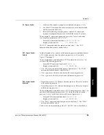
IDT - Set or Read the
Micro-Ion Gauge Delay
Time
The ion gauge delay time (IDT) command changes the amount of time the
Micro-Ion gauge waits to turn ON after pressure has decreased to a point
where the gauge can operate. This is useful to allow sufficient time for
corrosive gases to be pumped out of the chamber before the Micro-Ion
gauge hot filament is turned ON.
The example IDT command sets the additional delay time to 20 seconds.
Example IDT command from host:
#01IDT 20
↵
Response from module:
*01 PROGM OK
↵
• The command includes the alpha characters “I”, “D”, and “T” and the
numeric value representing the number of seconds.
• Valid values are 0 to 600 seconds.
• The Micro-Ion gauge will wait the number of seconds specified in the IDT
command,
plus
the software-defined delay, before turning on with
decreasing pressure.
• With increasing pressure, the Micro-Ion gauge will turn OFF when
pressure increases to 30 mTorr (3.99 x 10
–2
mbar, 3.99 pascal).
If you send the IDT command without the time value, the module returns a
character string that represents the Micro-Ion gauge delay time.
IDT command from host:
#01IDT
↵
Example response from module:
*01 60 IDT
↵
The example response means the delay time is set to 60 seconds. If the SF
command is set to T (tungsten), the response does
not
include the additional
software-determined delay.
During the delay, outputs indicate pressure as measured by the Conductron
sensor.
Содержание 356 Micro-Ion Plus Series
Страница 2: ......
Страница 24: ...24 Micro Ion Module Instruction Manual 356007 GP...
Страница 58: ...Chapter 3 58 Micro Ion Module Instruction Manual 356007 GP...
Страница 68: ...Appendix A 68 Micro Ion Module Instruction Manual 356007 GP Figure A 1 Automatic Filament Switching Flow Chart...
Страница 70: ...70 Micro Ion Module Instruction Manual 356007 GP Figure A 3 Manual Filament Switching Flow Chart...
Страница 74: ...Index 74 Micro Ion Module Instruction Manual 356007 GP...
Страница 75: ......