


Chapter 2
18
Micro-Ion
®
Module Instruction Manual - 356007-GP
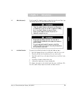
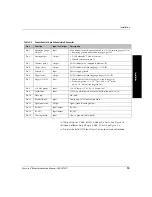
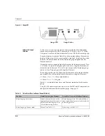
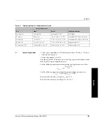
Figure 2-2
9-pin Trip Point and 15-pin User Interface Subminiature D Wiring Connectors
Module Power Supply
Connect the module power supply to terminals 5 and 8 on the 15-pin I/O
wiring connector.
• Pin 5 (ground) is negative (–).
• Pin 8 (power input) is positive (+).
The module requires a +24 Vdc ±15% external power supply. The power
supply must provide a 1.5 A current at 24 Vdc. Inrush current can
momentarily exceed the 1.5 A peak.
Typical module operating power is 18 W for 4 mA emission when the
Micro-Ion gauge is ON.
Power inputs are reverse-bias protected.
The Micro-Ion gauge will not activate and an emission error will occur if
insufficient power is supplied during Micro-Ion gauge activation.
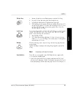
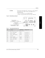
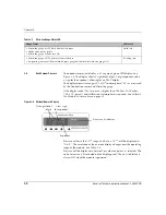
Analog and RS-485
Output Wiring
Connect wiring for analog and RS-485 outputs to the 15-pin
subminiature-D connector, as illustrated in Figure 2-3.
Figure 2-3
Wiring Terminals for Analog and RS-485 Wiring
9-pin subminiature D
trip points wiring
connector
15-pin subminiature
D user interface
connector
Pin 1 must be
connected to pin 5
for the Micro-Ion
gauge to turn ON
Содержание 356 Micro-Ion Plus Series
Страница 2: ......
Страница 24: ...24 Micro Ion Module Instruction Manual 356007 GP...
Страница 58: ...Chapter 3 58 Micro Ion Module Instruction Manual 356007 GP...
Страница 68: ...Appendix A 68 Micro Ion Module Instruction Manual 356007 GP Figure A 1 Automatic Filament Switching Flow Chart...
Страница 70: ...70 Micro Ion Module Instruction Manual 356007 GP Figure A 3 Manual Filament Switching Flow Chart...
Страница 74: ...Index 74 Micro Ion Module Instruction Manual 356007 GP...
Страница 75: ......