GDI ±
On-vehicle Service
13A-105
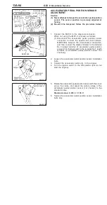
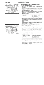
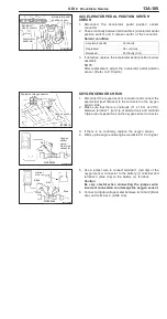
ACCELERATOR PEDAL POSITION SWITCH
CHECK
1.
Disconnect the accelerator pedal position sensor
connector.
2.
Check continuity between terminal No.4 (accelerator pedal
position switch) and 5 (sensor earth) of the connector.
Normal condition
Accelerator pedal
Continuity
Depressed
No continuity
Released
Continuity (0
Ω
)
3.
If defective, replace the accelerator pedal position sensor
assembly.
NOTE
After replacement, adjust the accelerator pedal position
sensor. (Refer to P.13A-94.)
OXYGEN SENSOR CHECK
1.
Disconnect the oxygen sensor connector and connect the
special tool (test harness) to the connector on the oxygen
sensor side.
2.
Make sure that there is continuity (11 ± 18
Ω
at 20
_
C)
between terminal 1 (red cip of special tool) and terminal
3 (blue clip of special tool) on the oxygen sensor connector.
3.
If there is no continuity, replace the oxygen sensor.
4.
Warm up the engine until engine coolant is 80
_
C or higher.
5.
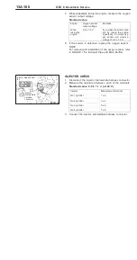
Use a jumper wire to connect terminal 1 (red clip) of the
oxygen sensor connector to the battery (+) terminal and
terminal 3 (blue clip) to the battery (±) terminal.
Caution
Be very careful when connecting the jumper wire;
incorrect connection can damage the oxygen sensor.
6.
Connect a digital voltage meter between terminal 2 (black
clip) and terminal 4 (white clip).
Equipment
side connector
Accelerator pedal
position sensor
Accelerator
pedal arm
Equipment side connector
Oxygen sensor
Blue
Red
MD998464
Oxygen
sensor
equip-
ment side
connector
Jumper
wire
Black
Red
White
MD998464
Blue
Содержание Pajero Pinin 1999
Страница 32: ...NOTES ...
Страница 73: ...13A 1 FUEL CONTENTS GASOLINE DIRECT INJECTION GDI 13A FUEL SUPPLY 13B ...
Страница 190: ...NOTES ...
Страница 191: ...13B 1 FUEL SUPPLY CONTENTS FUEL TANK 2 Fuel Pump Module 4 ...
Страница 214: ...NOTES ...
Страница 222: ...NOTES ...
Страница 256: ...NOTES ...
Страница 274: ...NOTES ...
Страница 282: ...NOTES ...
Страница 360: ...NOTES ...
Страница 412: ...NOTES ...
Страница 443: ...32 1 POWER PLANT MOUNT CONTENTS ENGINE MOUNTING 2 TRANSMISSION MOUNTING 3 ...
Страница 446: ...NOTES ...
Страница 447: ......
Страница 448: ......
Страница 449: ......
Страница 450: ......
Страница 451: ......
Страница 452: ......
Страница 453: ......
Страница 454: ......
Страница 455: ......
Страница 456: ......
Страница 457: ......
Страница 458: ......
Страница 459: ......
Страница 460: ......
Страница 461: ......
Страница 462: ...34 1 REAR SUSPENSION CONTENTS GENERAL INFORMATION 2 SPECIAL TOOLS 3 REAR SUSPENSION ASSEMBLY 4 ...
Страница 467: ...NOTES ...
Страница 468: ...BASIC BRAKE SYSTEM 35A ANTI SKID BRAKING SYSTEM ABS 4WD 35B 35A 1 SERVICE BRAKES CONTENTS ...
Страница 499: ...NOTES ...
Страница 531: ...NOTES ...
Страница 541: ...NOTES ...
Страница 554: ...STEERING Steering Wheel and Shaft 37A 13 REMOVAL SERVICE POINTS AA STEERING WHEEL REMOVAL MB990803 ...
Страница 649: ...NOTES ...
Страница 650: ...INTERIOR 52A SUPPLEMENTAL RESTRAINT SYSTEM SRS 52B 52A 1 INTERIOR AND SUPPLEMENTAL RESTRAINT SYSTEM SRS CONTENTS ...
Страница 728: ...54A 1 CHASSIS ELECTRICAL CONTENTS CHASSIS ELECTRICAL 54A SMART WIRING SYSTEM SWS 54B ...
Страница 836: ...54B 1 SMART WIRING SYSTEM SWS CONTENTS GENERAL INFOMATION 54B 1 SPECIAL TOOLS 54B 5 TROUBLESHOOTING 54B 6 ...
Страница 883: ...NOTES ...
Страница 919: ...NOTES ...


