GDI ±
On-vehicle Service
GDI ±
On-vehicle Service
13A-97
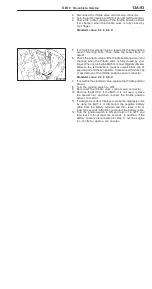
14. Release residual pressure from the fuel pipe line. (Refer to
P.13A-99.)
15. Remove the fuel pressure gauge and special tools from the
fuel pump (high pressure).
Caution
Cover the hose connection with rags to prevent splash
of fuel that could be caused by some residual pressure
in the fuel pipe line.
16. Replace the O-ring at the end of the high-pressure fuel
hose with a new one. Furthermore, apply engine oil to
the new O-ring before replacement.
17. Fit the high-pressure fuel hose to the fuel pump (high
pressure) and tighten the mounting bolt to specified torque.
18. Check for any fuel leaks by following the procedure in
step 7.
19. Disconnect the MUT-
II
.
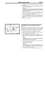
MEASUREMENT OF FUEL HIGH PRESSURE BETWEEN
FUEL PUMP (HIGH PRESSURE) AND INJECTORS
NOTE
Measurement of the fuel pressure between the fuel pump
(high pressure) and the injectors should be carried out after
checking that the fuel pressure between the fuel pump (low
pressure) and the fuel pump (high pressure) is normal.
1.
Connect the MUT-
II
to the diagnosis connector.
2.
Disconnect the injector intermediate harness connector.
3.
Turn the ignition switch to ON.
4.
Select ªItem No.74º from the MUT-
II
Data list.
5.
Crank the engine continuously for 2 seconds or more,
and visually check that there are no fuel leaks from any
parts.
Caution
If any fuel leaks appear, stop cranking immediately
and repair the source of the leak.
6.
Crank the engine, and then measure the fuel pressure
immediately after 20 seconds.
Limit: Minimum 1 MPa
Caution
If the fuel pressure is less than 1 MPa, there may
be a partial fuel leak in the high-pressure fuel system.
7.
Turn the ignition switch to OFF.
8.
Connect the injector intermediate harness connector.
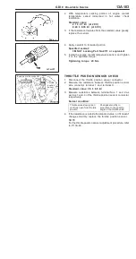
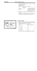
Injector
intermediate
harness
connector
Содержание Pajero Pinin 1999
Страница 32: ...NOTES ...
Страница 73: ...13A 1 FUEL CONTENTS GASOLINE DIRECT INJECTION GDI 13A FUEL SUPPLY 13B ...
Страница 190: ...NOTES ...
Страница 191: ...13B 1 FUEL SUPPLY CONTENTS FUEL TANK 2 Fuel Pump Module 4 ...
Страница 214: ...NOTES ...
Страница 222: ...NOTES ...
Страница 256: ...NOTES ...
Страница 274: ...NOTES ...
Страница 282: ...NOTES ...
Страница 360: ...NOTES ...
Страница 412: ...NOTES ...
Страница 443: ...32 1 POWER PLANT MOUNT CONTENTS ENGINE MOUNTING 2 TRANSMISSION MOUNTING 3 ...
Страница 446: ...NOTES ...
Страница 447: ......
Страница 448: ......
Страница 449: ......
Страница 450: ......
Страница 451: ......
Страница 452: ......
Страница 453: ......
Страница 454: ......
Страница 455: ......
Страница 456: ......
Страница 457: ......
Страница 458: ......
Страница 459: ......
Страница 460: ......
Страница 461: ......
Страница 462: ...34 1 REAR SUSPENSION CONTENTS GENERAL INFORMATION 2 SPECIAL TOOLS 3 REAR SUSPENSION ASSEMBLY 4 ...
Страница 467: ...NOTES ...
Страница 468: ...BASIC BRAKE SYSTEM 35A ANTI SKID BRAKING SYSTEM ABS 4WD 35B 35A 1 SERVICE BRAKES CONTENTS ...
Страница 499: ...NOTES ...
Страница 531: ...NOTES ...
Страница 541: ...NOTES ...
Страница 554: ...STEERING Steering Wheel and Shaft 37A 13 REMOVAL SERVICE POINTS AA STEERING WHEEL REMOVAL MB990803 ...
Страница 649: ...NOTES ...
Страница 650: ...INTERIOR 52A SUPPLEMENTAL RESTRAINT SYSTEM SRS 52B 52A 1 INTERIOR AND SUPPLEMENTAL RESTRAINT SYSTEM SRS CONTENTS ...
Страница 728: ...54A 1 CHASSIS ELECTRICAL CONTENTS CHASSIS ELECTRICAL 54A SMART WIRING SYSTEM SWS 54B ...
Страница 836: ...54B 1 SMART WIRING SYSTEM SWS CONTENTS GENERAL INFOMATION 54B 1 SPECIAL TOOLS 54B 5 TROUBLESHOOTING 54B 6 ...
Страница 883: ...NOTES ...
Страница 919: ...NOTES ...


