


GDI ±
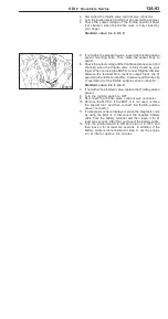
On-vehicle Service
13A-93
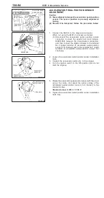
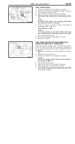
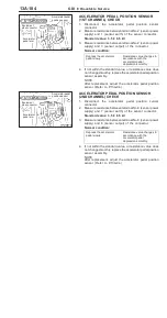
2.
Disconnect the throttle valve control servo connector.
3.
Turn the ignition switch to ON (but do not start the engine).
4.
Check the output voltage of the throttle position sensor
(1st channel) when the throttle valve is fully closed by
your finger.
Standard value: 0.4 ± 0.6 V
5.
If not within the standard value, loosen the throttle position
sensor mounting bolts. Then rotate the sensor body to
adjust.
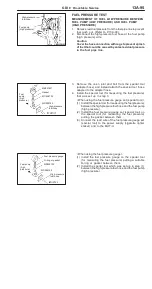
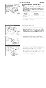
6.
Check the output voltage of the throttle position sensor (2nd
channel) when the throttle valve is fully closed by your
finger. When not using the MUT-
II
, connect digital voltmeter
between the terminal No.4 (sensor output: black clip of
special tool) and the terminal No.3 (sensor earth: white clip
of special tool) of the throttle position sensor connector.
Standard value: 4.2 ± 4.8 V
7.
If not within the standard value, replace the throttle position
sensor.
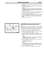
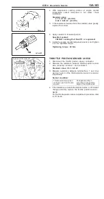
8.
Turn the ignition switch to OFF.
9.
Reconnect the throttle valve control servo connector.
10. Remove the MUT-
II
. If the MUT-
II
is not used, remove
the special tool, and then connect the throttle position
sensor connector.
11. If a diagnosis code is displayed, erase the diagnosis code
by using the MUT-
II
or disconnect the negative battery
cable from the battery terminal and then leave it for at
least ten seconds. After that, reconnect the battery cable.
12. Turn the ignition switch to ON and return it to OFF, and
then leave it for at least ten seconds. In addition, if the
battery cable is disconnected at step 11, let the engine
run at idle for approx. ten minutes.
Содержание Pajero Pinin 1999
Страница 32: ...NOTES ...
Страница 73: ...13A 1 FUEL CONTENTS GASOLINE DIRECT INJECTION GDI 13A FUEL SUPPLY 13B ...
Страница 190: ...NOTES ...
Страница 191: ...13B 1 FUEL SUPPLY CONTENTS FUEL TANK 2 Fuel Pump Module 4 ...
Страница 214: ...NOTES ...
Страница 222: ...NOTES ...
Страница 256: ...NOTES ...
Страница 274: ...NOTES ...
Страница 282: ...NOTES ...
Страница 360: ...NOTES ...
Страница 412: ...NOTES ...
Страница 443: ...32 1 POWER PLANT MOUNT CONTENTS ENGINE MOUNTING 2 TRANSMISSION MOUNTING 3 ...
Страница 446: ...NOTES ...
Страница 447: ......
Страница 448: ......
Страница 449: ......
Страница 450: ......
Страница 451: ......
Страница 452: ......
Страница 453: ......
Страница 454: ......
Страница 455: ......
Страница 456: ......
Страница 457: ......
Страница 458: ......
Страница 459: ......
Страница 460: ......
Страница 461: ......
Страница 462: ...34 1 REAR SUSPENSION CONTENTS GENERAL INFORMATION 2 SPECIAL TOOLS 3 REAR SUSPENSION ASSEMBLY 4 ...
Страница 467: ...NOTES ...
Страница 468: ...BASIC BRAKE SYSTEM 35A ANTI SKID BRAKING SYSTEM ABS 4WD 35B 35A 1 SERVICE BRAKES CONTENTS ...
Страница 499: ...NOTES ...
Страница 531: ...NOTES ...
Страница 541: ...NOTES ...
Страница 554: ...STEERING Steering Wheel and Shaft 37A 13 REMOVAL SERVICE POINTS AA STEERING WHEEL REMOVAL MB990803 ...
Страница 649: ...NOTES ...
Страница 650: ...INTERIOR 52A SUPPLEMENTAL RESTRAINT SYSTEM SRS 52B 52A 1 INTERIOR AND SUPPLEMENTAL RESTRAINT SYSTEM SRS CONTENTS ...
Страница 728: ...54A 1 CHASSIS ELECTRICAL CONTENTS CHASSIS ELECTRICAL 54A SMART WIRING SYSTEM SWS 54B ...
Страница 836: ...54B 1 SMART WIRING SYSTEM SWS CONTENTS GENERAL INFOMATION 54B 1 SPECIAL TOOLS 54B 5 TROUBLESHOOTING 54B 6 ...
Страница 883: ...NOTES ...
Страница 919: ...NOTES ...


