DISASSEMBLY PROCEDURE
PHOTOS
91
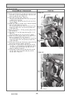
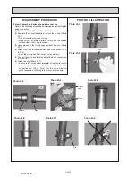
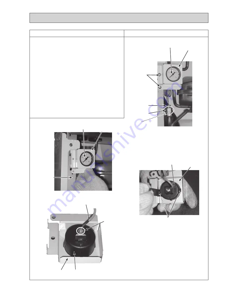
Photo 11-1
11. How to remove the pressure relief valve/manometer/air
vent (automatic)
(1) Remove the front panel (Refer to Procedure 1).
(2)
Swing the control box to the front (Refer to Procedure 4).
<Manometer>
(3) Remove the G1/4" nut from the pressure relief valve
using 2 spanners: one to hold the joint (G1/4") and the
other to turn the manometer connection. (Photo 11-1)
• When reinstalling the G1/4" nut, use a new G1/4"
gasket. (Photo 11-1)
(4)
Remove the 2 screws and remove the manometer cover
with the manometer from the front frame (L) by sliding it
upward. (Photos 11-1 and 11-2)
(5) Remove the manometer from the manometer cover while
pressing on the 2 claws. (Photo 11-3)
• When reinstalling the manometer assembly on the unit,
beware not to put strain on the root of the capillary tube
as the capillary tube is easy to break at the root. (Photo
11-4)
Photo 11-2
Photo 11-3
Manometer
Manometer
cover
Screws
Photo 11-4
Manometer
connection (
G1/4")
Joint (
G1/4")
Gasket
(
G1/4")
Manometer
Manometer
cover
Front frame (L)
Manometer
Manometer
cover
Claws
Manometer
Manometer
cover
Root
Capillary tube
Continue to the next page.
OCH570C
Содержание EHPT20X-MHCW
Страница 108: ......

