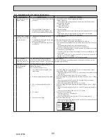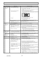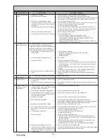
PHOTOS
81
Bracket (R)
DISASSEMBLY PROCEDURE
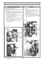
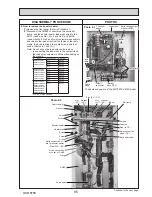
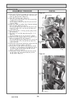
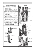
Photo 4-1
Photo 4-3
4. How to remove the control box
(1) Remove the front panel (Refer to Procedure 1).
(2) Disconnect only the lead wires in the control box that
connect to the components in the cylinder unit.
Photo 4-2 shows the control box before the related lead
wires are disconnected.
(3) Remove the 3 screws on the bracket (L and R) and
disengage the tab on the control box bracket from the
front frame (L). (Photo 4-1)
(4) Disengage the 2 tabs on the control box bracket (R) from
the front frame (R). (Photo 4-1)
(5) Slightly lift and pull out the control box from the cylinder
unit while tilting the control box backward.
<When swinging the control box to the front>
(2)
Remove the 3 screws on the bracket (L and R). (Photo 4-1)
(3) Disengage the tab on the control box bracket (L) from
the front frame (L) and pull the control box by lifting the
left-hand side to swing the control box. (Photo 4-3)
Note: Disconnect the field wiring as necessary.
The photos shown are of the EHST20C-YM9C model.
Control box
Front
frame (R)
Swing
Bracket (L)
Cable
clamps
Cable
strap
Photo 4-2
Screw
Front
frame (L)
The photos shown are of the EHST20C-VM6C model with
optional immersion heater.
Screw
Control
box
Tab
Tab
Tab
Fastener
CN1A connector
CNV1
connector
CNPWM connector
CNP4
connector
CNP1
connector
Earth cable of
water pump
(primary circuit)
Earth cable of
water pump
(sanitary circuit)
Cable
strap
Screw
OCH570C
Содержание EHPT20X-MHCW
Страница 108: ......


