PHOTOS
DISASSEMBLY PROCEDURE
84
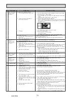
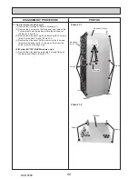
7. How to remove the flow sensor
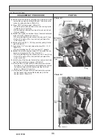
(1) Remove the front panel (Refer to Procedure 1).
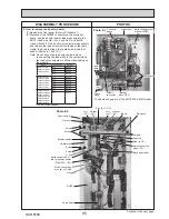
(2) Disconnect the CN1A connector on the controller board.
(Photo 4-2)
(3) Release the flow sensor lead wire from the cable clamp,
the fastener and the cable strap in the control box, and
the cable strap, the coated clamp and the 3 bands below
the control box. (Photos 4-1 and 10-1)
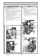
(4) Close (OFF) the strainer valve. (Photo 5-1)
• When the strainer valve handle is stiff, use a tool to grip
the handle and turn it carefully.
• When opening or closing the strainer valve, ensure to do
so fully, not halfway.
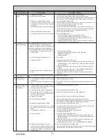
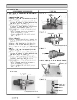
(5) Loosen the nuts using 2 spanners, and remove the flow
sensor; one to hold the flow sensor and the other to turn
the nut. (Photos 7-1 and 7-2)
• When reinstalling the flow sensor, use new O-rings.
(Photos 7-1 and 7-2)
Photo 7-1
Photo 7-2
Sensor part
O-ring
Lead wire
Nut (G1")
O-ring
Place to hold
the flow sen
-
sor with a
spanner
Flow direction
Nut (G1")
O-ring
Flow sensor
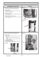
Photo 7-3
Photo 7-4
Sensor part
Lead wire
O-ring
Flow direction
O-rings
Flow sensor
R2 models
Same diameter
quick connection
O-ring
<For R2 models>
(5) Remove the flow sensor by detaching the same
diameter quick connection. (Photos 7-3 and 7-4)
• When reinstalling the flow sensor, use new O-rings.
(Photos 7-3 and 7-4)
• Refer to Procedure 23 for how to attach and
detach the quick connection.
Note: Set the flow sensor in the direction of the arrow
printed on the flow sensor, and in the way that the
sensor part faces to the left (right for R2 models).
(Photo 7-1 and 7-3)
Same diameter
quick connection
OCH570C
Содержание EHPT20X-MHCW
Страница 108: ......

