background image

73

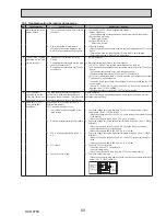
No.

Fault symptom 

Possible cause

Explanation - Solution

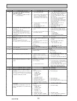
22

Water discharges from 

expansion relief valve 

- part of Inlet Control 

Group

(EH*T20*-MHCW only) 

(sanitary circuit)

1. 

If continual – field supplied pressure 

reducing valve not working.

1. 

Check function of pressure reducing valve and replace if necessary.

2.

If continual – expansion relief valve may be 

damaged.

2.

Turn the handle on the expansion relief valve to check for foreign objects 

inside. If the problem is not still solved, replace the expansion relief valve 

with a new one.

3.

If intermittent – expansion vessel charge 

may have reduced/bladder perished.

3.

Check gas-side pressure in expansion vessel.

Recharge to correct precharge pressure if necessary.

If bladder perished replace expansion vessel with a new one with 

appropriate precharge.

4.

DHW tank may have subjected to backflow.

4.

Check pressure in DHW tank. If pressure in DHW tank is similar to that in 

the incoming mains, cold water supply that merges with incoming mains 

water supply could flow back to DHW tank. Investigate source of back-

feed and rectify error in pipework/fitting configuration. Adjust pressure in 

cold supply.

5.

Unit has overheated – thermal controls have 

failed.

5.

Switch off power to the heat pump and immersion heaters. Leave water 

running. Wait until discharge stops. Isolate water supply and replace if 

faulty.

23

Noisy water circulation 

pump

Air in water circulation pump.

Use manual and automatic air vents to remove air from system.

Top up water if necessary to achieve 1 bar on primary circuit.

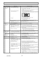
24

Noise during hot water 

draw off typically 

worse in the morning.

1. 

Loose airing cupboard pipework.

1.

Install extra pipe fastening clips.

2.

Heaters switching on/off.

2.

Normal operation no action necessary.

25 Mechanical noise 

heard coming from the 

cylinder unit.

1. 

Heaters switching on/off.

Normal operation no action necessary.

2.

3-way  valve  changing  position  between 

DHW and heating mode.

26 Water circulation pump 

runs for a short time 

unexpectedly.

Water circulation pump jam prevention mechanism 

(routine) to inhibit the build-up of scale.

Normal operation no action necessary.

27

Milky/Cloudy water

(Sanitary circuit)

Oxygenated water

Water from any pressurised system will release oxygen bubbles when water is 

running. The bubbles will settle out.

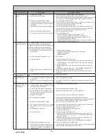
28

Heating mode has 

been on standby for 

a long time (does 

not start operation 

smoothly.)

The time of “Delay” set in “Economy settings 

for pump” is too short. (Go to “Service menu” 

→ “Auxiliary settings” → “Economy settings for 

pump”).

Increase the time of “Delay” in “Economy settings for pump” .

29 The cylinder unit 

that was running in 

the heating mode 

before power failure 

is running in the DHW 

mode after power 

recovery.

The cylinder unit is designed to run in an operation 

mode with a higher priority (i.e. DHW mode in this 

case) at power recovery.

• Normal operation.

•  After the DHW max. operation time has elapsed or the DHW max. temperature 

has been reached, the DHW mode switches to the other mode (ex. Heating 

mode).

30

Cooling mode is NOT 

available.

DIP SW2-4 is OFF.

Turn DIP SW2-4 to ON. (Refer to “6-19. DIP switch functions”.)

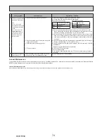
31

The cooling system 

does not cool down to 

the set temperature.

1.

When the water in the circulation circuit is un

-

duly hot, Cooling mode starts with a delay for 

the protection of the outdoor unit.

1.

Normal operation.

2. When the outdoor ambient temperature is 

lower than the preset temperature that acti

-

vates the freeze stat function, Cooling mode 

does not start running.

2.

To run Cooling mode overriding the freeze stat function, adjust the preset 

temperature that activates the freeze stat function. 

(Refer to "<Freeze stat function>" on Page 49.)

32 The electric heaters are 

activated shortly after 

DHW or LP mode starts 

running after Cooling 

mode.

The setting time period of Heat-pump-only opera

-

tion is short.

Adjust the setting time period of Heat-pump only operation. (Refer to “<Electric 

heater (DHW)> on Page 47.

33

During DHW or LP 

mode following the 

cooling mode, error 

L6 (circulation water 

freeze protection error ) 

occurs and the system 

stops all the operations.

The unit runs in Cooling mode when the outdoor 

ambient temperature is lower than 10ºC (outside 

of the guaranteed operating range).

(When defrosting operation is running at such a 

low outdoor ambient temperature after Cooling 

mode is switched to DHW or LP mode, the water 

temperature in the cooling circuit drops too low, 

which could result in L6 error to stop all the opera

-

tions.

Do not run Cooling operation when the outdoor ambient temperature is lower 

than 10ºC.

To automatically stop or recover only Cooling operation and keep other opera

-

tions running, the freeze stat function can be used. Set the preset temperature 

that activates the freeze stat function to adjust the outdoor ambient tempera

-

ture as follows. (Refer to "<Freeze stat function>" on Page 49.)

Outdoor ambient temperature

Cooling operation

3ºC higher than the preset temperature

Stop

5ºC higher than the preset temperature

Recover

OCH570C

Содержание EHPT20X-MHCW

Страница 1: ...C EHST20C VM6C EHST20C YM9C EHST20C TM9C EHST20C VM2EC EHST20C VM6EC EHST20C YM9EC EHST20C MHCW EHST20C MEC EHST20D VM2C EHST20D VM2EC EHST20D YM9C EHST20D MHCW EHST20D MEC EHST20D MHC Revision Added...

Страница 2: ...MHCWR1 UK EHST20C MECR1 UK EHST20D VM2CR1 UK EHST20D VM2ECR1 UK EHST20D YM9CR1 UK EHST20D MHCWR1 UK EHST20D MECR1 UK EHST20D MHCR1 UK EHPT20X VM2CR1 UK EHPT20X VM6CR1 UK EHPT20X YM9CR1 UK EHPT20X TM9...

Страница 3: ...BS PUHZ HW140VHA BS PUHZ HW140VHA2 BS PUHZ HW140VHA2R1 BS PUHZ HW140VHA2R2 BS PUHZ HW140VHA2R3 BS PUHZ HW140VHA2R4 BS PUHZ HW140VHA2R5 BS PUHZ SW40 50VHA BS OCH525 PUHZ SW40 50VHAR1 BS PUHZ SW50VKA B...

Страница 4: ...ing or servicing the cylinder unit use only the specified refrigerant R410A to charge the refrigerant lines Do not mix it with any other refrigerant and do not allow air to remain in the lines If air...

Страница 5: ...use thin pipes Refer to section 4 4 in the installation manual Store the pipes to be used during installation indoors and keep both ends of the pipes sealed until just before brazing Leave elbow join...

Страница 6: ...ing should be performed with the cylinder of syphon stood vertically Refrigerant is charged from liquid phase 3 Service tools Use the service tools below as exclusive tools for R410A refrigerant No To...

Страница 7: ...6 kg 6 6 kg 6 6 kg 6 6 kg 6 6 kg 5 7 kg 5 7 kg 5 7 kg 5 7 kg 5 7 kg Plate heat exchanger MWA2 Plate heat exchanger MWA1 Unvented expansion vessel Primary heating Nominal volume 12 L 12 L 12 L 12 L Cha...

Страница 8: ...pec table Cooling See outdoor unit spec table min 10 C 3 DHW tank performance Maximum allowable hot water temperature 4 70 C 4 70 C Time to raise DHW tank temp 15 65 C 5 22 75 min Time to reheat 70 of...

Страница 9: ...2 kg 306 kg 314 kg Water volume of heating circuit in the unit 1 6 6 kg 6 6 kg 6 6 kg 6 6 kg 6 6 kg 6 6 kg 6 6 kg 6 6 kg 5 7 kg 5 7 kg 5 7 kg 5 7 kg 5 7 kg Plate heat exchanger MWA2 Plate heat exchang...

Страница 10: ...nteed operating range Ambient 2 0 35 C 80 RH Outdoor temperature Heating See outdoor unit spec table Cooling See outdoor unit spec table min 10 C 3 DHW tank performance Maximum allowable hot water tem...

Страница 11: ...pump 1 Primary circuit 15 Pump valve 16 DHW tank 17 Plate heat exchanger Water Water 18 Scale trap 19 Water circulation pump Sanitary circuit 20 Immersion heater 21 Temperature and pressure relief val...

Страница 12: ...ump Sanitary circuit 20 Immersion heater 21 Temperature and pressure relief valve 22 Pressure relief valve 10bar DHW Tank 23 Drain cock DHW tank 24 Drain cock Sanitary circuit 25 Flow water temp therm...

Страница 13: ...ection No plate heat exchanger 28 mm Compression G Refrigerant GAS With plate heat exchanger 12 7 mm Flare E ST20D 15 88 mm Flare E ST20C H Refrigerant LIQUID With plate heat exchanger 6 35 mm Flare E...

Страница 14: ...be left for the provision of discharge pipework as detailed in National and Local Building Regulations The cylinder unit must be located indoors and in a frost free environment for example in a utili...

Страница 15: ...Return water temp THW5 Thermistor DHW tank water temp THW6 Thermistor Zone1 flow temp Option THW7 Thermistor Zone1 return temp Option THW8 Thermistor Zone2 flow temp Option THW9 Thermistor Zone2 retur...

Страница 16: ...on use the main remote controller to select Boiler in External input setting screen in the service menu Table 2 Outputs Name Terminal block Connector Item OFF ON OUT1 TBO 1 1 2 CNP1 Water circulation...

Страница 17: ...temp Option THW9 Thermistor Zone2 return temp Option THWB1 Thermistor Boiler flow temp Option THWB2 Thermistor Boiler return temp Option IN1 Room thermostat 1 Local supply IN2 Flow switch 1 Local supp...

Страница 18: ...To turn on the boiler operation use the main remote controller to select Boiler in External input setting screen in the service menu Table 2 Outputs Name Terminal block Connector Item OFF ON OUT1 TBO...

Страница 19: ...be sure to check the outdoor unit electric wiring diagram for service Table 1 Signal Inputs Name Terminal block Connector Item OFF Open ON Short IN1 TBI 1 13 14 Room thermostat 1 input Refer to SW2 1...

Страница 20: ...Option THW8 Thermistor Zone2 flow temp Option THW9 Thermistor Zone2 return temp Option THWB1 Thermistor Boiler flow temp Option THWB2 Thermistor Boiler return temp Option IN1 Room thermostat 1 Local s...

Страница 21: ...liquid temp THW1 Thermistor Flow water temp THW2 Thermistor Return water temp THW5 Thermistor DHW tank water temp THW6 Thermistor Zone1 flow temp Option THW7 Thermistor Zone1 return temp Option THW8 T...

Страница 22: ...the main remote controller to select Boiler in External input setting screen in the service menu Table 2 Outputs Name Terminal block Connector Item OFF ON OUT1 TBO 1 1 2 CNP1 Water circulation pump 1...

Страница 23: ...e1 return temp Option THW8 Thermistor Zone2 flow temp Option THW9 Thermistor Zone2 return temp Option THWB1 Thermistor Boiler flow temp Option THWB2 Thermistor Boiler return temp Option IN1 Room therm...

Страница 24: ...e reduced 2 To turn on the boiler operation use the main remote controller to select Boiler in External input setting screen in the service menu Table 2 Outputs Name Terminal block Connector Item OFF...

Страница 25: ...Contactor for booster heater 2 BHCP Contactor for booster heater protection Table 1 Signal Inputs Name Terminal block Connector Item OFF Open ON Short IN1 TBI 1 13 14 Room thermostat 1 input Refer to...

Страница 26: ...rn temp Option THW8 Thermistor Zone2 flow temp Option THW9 Thermistor Zone2 return temp Option THWB1 Thermistor Boiler flow temp Option THWB2 Thermistor Boiler return temp Option IN1 Room thermostat 1...

Страница 27: ...THWB2 Thermistor Boiler return temp Option IN1 Room thermostat 1 Local supply IN2 Flow switch 1 Local supply IN3 Flow switch 2 Local supply IN4 Demand control Local supply IN5 Outdoor thermostat Local...

Страница 28: ...remote controller to select Boiler in External input setting screen in the service menu Table 2 Outputs Name Terminal block Connector Item OFF ON OUT1 TBO 1 1 2 CNP1 Water circulation pump 1 output S...

Страница 29: ...and control Local supply IN5 Outdoor thermostat Local supply IN6 Room thermostat 2 Local supply IN7 Flow switch 3 Local supply IN8 Electric energy meter 1 Local supply IN9 Electric energy meter 2 Loca...

Страница 30: ...e2 Refer to SW3 3 in 6 19 DIP switch functions IN8 TBI 3 1 2 Electric energy meter 1 Refer to installation manual IN9 TBI 3 3 4 Electric energy meter 2 IN10 TBI 3 5 6 Heat meter 1 If using outdoor the...

Страница 31: ...TBI 3 1 2 Electric energy meter 1 Refer to installation manual IN9 TBI 3 3 4 Electric energy meter 2 IN10 TBI 3 5 6 Heat meter IN1A TBI 3 12 14 CN1A Flow sensor 1 If using outdoor thermostat for contr...

Страница 32: ...rol Local supply IN5 Outdoor thermostat Local supply IN6 Room thermostat 2 Local supply IN7 Flow switch 3 Local supply IN8 Electric energy meter 1 Local supply IN9 Electric energy meter 2 Local supply...

Страница 33: ...tion Inactive Active OFF Except EH T20 VM2 C ON EH T20 VM2 C SW2 4 Cooling mode function Inactive Active OFF EH T20 M C ON ERST20 M C SW2 5 Automatic switch to backup heat source operation When outdoo...

Страница 34: ...4 230 V AC Cylinder unit Outdoor unit S2 S3 4 24 V DC 2 A breaker with at least 3 0 mm contact separation in each pole shall be provided Use earth leakage breaker NV The breaker shall be provided to...

Страница 35: ...at least 3 0 mm contact separation in each pole shall be provided Use earth leakage breaker NV The breaker shall be provided to ensure disconnection of all active phase conductors of the supply 3 Max...

Страница 36: ...ter heater Primary circuit N 230 V 50 Hz 2 kW 16 A 2 2 5 mm 6 kW 32 A 2 6 0 mm Immersion heater DHW tank N 230 V 50 Hz 3 kW 16 A 2 2 5 mm Cylinder unit power supply N 230 V 50 Hz Cylinder unit input c...

Страница 37: ...size must comply with the applicable local and national codes 2 Indoor unit outdoor unit connecting cords shall not be lighter than polychloroprene sheathed flexible cord Design 60245 IEC 57 Indoor u...

Страница 38: ...ay damage the pipework Flare connection Flare connection Cylinder unit Cylinder unit Drain Drain Drain Drain Drain Drain Cold water Cold water DHW DHW Local system Refrigerant pipe Water pipe Local sy...

Страница 39: ...Operating pressure Potable side 3 5 bar 3 5 bar 3 5 bar Expansion vessel charge setting pressure Potable side 3 5 bar 3 5 bar 3 5 bar Expansion valve setting pressure Potable side 6 0 bar 6 0 bar 6 0...

Страница 40: ...ixing tank local supply 3 Zone1 flow water temp thermistor THW6 4 Zone1 return water temp thermistor THW7 5 Zone1 water circulation pump local supply 6 Zone1 flow switch local supply 7 Motorized mixin...

Страница 41: ...lush drain the water contents to remove any residue impurities resulting from the installation works Use the cylinder drain cock to safely discharge the warmed water to drain via a suitable hose 3 On...

Страница 42: ...ing 3 Electric heater When this icon is displayed the Electric heaters booster or immersion heater are in use 4 Target temperature Target flow temperature Target room temperature Compensation curve 5...

Страница 43: ...highlighted icon will appear as a larger version of the center of the screen Press CONFIRM to select and edit the highlighted mode Follow the Main remote controller Menu Tree for further setting usin...

Страница 44: ...eating room temp Heating flow temp Heating compensation curve Cooling flow temp Compensation curve preview Compensation curve edit F1 F1 F3 F1 F2 F2 F2 F2 F4 F3 F3 F3 F4 F4 F3 F4 F2 F4 F3 F4 F2 F3 F4...

Страница 45: ...nt ON OFF Hybrid settings Ambient Energy price CO2 emission Heat source Schedule Electricity Electricity Heat pump capacity ON OFF Electric heater capacity Demand control IN4 Main controller SD Yes No...

Страница 46: ...eration is selected a small timer icon appears in the screen The function selected will only remain in manual operation for a maximum of 2 hours This is to prevent accidental permanent override of the...

Страница 47: ...ed at Flow sensor Maximum The maximum flow rate to be detected at Flow sensor 1 Decreasing time before pump switched off may increase the duration of stand by in Heating Cooling mode 2 Set the Running...

Страница 48: ...ump speed 1 From the Service menu highlight Pump speed 2 Press CONFIRM 3 Press F3 and F4 buttons to select a refrigerant address of which you wish to configure or check the settings and press CONFIRM...

Страница 49: ...in the Flow temp range menu Fast mode is not efficient and will increase running cost compared to normal mode Range of outdoor ambient temperature at which simultaneous operation starts is 30 to 10 C...

Страница 50: ...0kW EHST20D YM9C 3 kW 6 kW 0kW ERST20C MEC 0kW 0kW 0kW ERST20C VM2C 2 kW 0kW 0kW ERST20D MEC 0kW 0kW 0kW ERST20D VM2C 2 kW 0kW 0kW EHPT20X VM2C 2 kW 0kW 0kW EHPT20X VM6C 2 kW 4 kW 0kW EHPT20X YM9C 3...

Страница 51: ...outdoor units control system only Thermistor reading This function shows the current readings of thermistors located on the water and refrigerant circuit Thermistor Description Thermistor Description...

Страница 52: ...on curve FSout Freeze stat function ambient temperature COR CO Cooling flow temperature Error history Error history allows the service engineer to view previous Error codes the unit address and the da...

Страница 53: ...te appears 1 For multiple outdoor units control system only Completion screen Resetting the password If you forget the password you entered or have to service a unit somebody else installed you can re...

Страница 54: ...Accumulated operating time reset 504 Indoor unit Zone1 room temp TH1A 39 88 C 505 Indoor unit Ref liquid temp TH2 39 88 C 506 Indoor unit Return water temp THW2 39 88 C 507 Indoor unit Zone2 room temp...

Страница 55: ...1 1 1 0 0 00 3A 1 1 0 1 1 1 0 0 00 3B 0 0 1 1 1 1 0 0 00 3C 1 0 1 1 1 1 0 0 00 3D 0 1 1 1 1 1 0 0 00 3E 1 1 1 1 1 1 0 0 00 3F 0 OFF 1 ON SW1 SW2 SW3 SW4 SW5 Display 1 2 3 4 5 6 7 8 0 0 0 0 0 0 1 0 00...

Страница 56: ...1 1 1 0 1 00 BA 1 1 0 1 1 1 0 1 00 BB 0 0 1 1 1 1 0 1 00 BC 1 0 1 1 1 1 0 1 00 BD 0 1 1 1 1 1 0 1 00 BE 1 1 1 1 1 1 0 1 00 BF 0 OFF 1 ON SW1 SW2 SW3 SW4 SW5 Display 1 2 3 4 5 6 7 8 0 0 0 0 0 0 1 1 00...

Страница 57: ...38 1 0 0 1 1 1 0 0 xx 39 0 1 0 1 1 1 0 0 xx 3A 1 1 0 1 1 1 0 0 xx 3B 0 0 1 1 1 1 0 0 xx 3C 1 0 1 1 1 1 0 0 xx 3D 0 1 1 1 1 1 0 0 xx 3E 1 1 1 1 1 1 0 0 xx 3F 0 OFF 1 ON OUT Display 1 2 3 4 5A 5B 6 7 0...

Страница 58: ...B8 1 0 0 1 1 1 0 1 xx B9 0 1 0 1 1 1 0 1 xx BA 1 1 0 1 1 1 0 1 xx BB 0 0 1 1 1 1 0 1 xx BC 1 0 1 1 1 1 0 1 xx BD 0 1 1 1 1 1 0 1 xx BE 1 1 1 1 1 1 0 1 xx BF 0 OFF 1 ON OUT Display 1 2 3 4 5A 5B 6 7 0...

Страница 59: ...xx 0 0 0 1 1 1 0 0 38 xx 1 0 0 1 1 1 0 0 39 xx 0 1 0 1 1 1 0 0 3A xx 1 1 0 1 1 1 0 0 3B xx 0 0 1 1 1 1 0 0 3C xx 1 0 1 1 1 1 0 0 3D xx 0 1 1 1 1 1 0 0 3E xx 1 1 1 1 1 1 0 0 3F xx Displayed only when t...

Страница 60: ...1 1 1 0 0 00 3E 1 1 1 1 1 1 0 0 00 3F Input signal display Request code 176 554 Please refer to Table 1 on relevant wiring diagram whilst using the following 0 OFF open 1 ON short IN Display 1 2 3 4 5...

Страница 61: ...s now deactivated Emergency operation In emergency operation an operation without connecting outdoor unit and main remote controller is possible When in Emergency operation the main control has NO con...

Страница 62: ...mena 3 If no obvious problem can be found continue to operate the unit NOTE Electrical components should only be replaced as a final option Please follow instructions in 10 4 Self diagnosis and action...

Страница 63: ...water circuit for leaks Check that the flow amount is within the recommended range 3 Valve operation fault 3 Check valves on primary water circuit are installed level 4 2 way valve local supply actuat...

Страница 64: ...Main remote controller or Room RC 1 8 is chosen for the Room Sensor setting in the Initial setting 4 Replace wireless remote controller or main remote controller 5 Incorrect setting of the DIP switch...

Страница 65: ...cient system head 1 Refer to table in 10 6 Checking Com ponent Parts Function to determine if system pump meets requirements If more head required either add a pump of the same size or replace existin...

Страница 66: ...status of the boiler 5 FTC board failure 5 Replace board LF Flow sensor failure Disconnection or loose connection of flow sensor Check flow sensor cable for damage or loose con nections LH Boiler circ...

Страница 67: ...g 1 or 2 breakers depending if the unit is powered indepen dently from the outdoor unit If the E3 E5 code is still displayed the FTC and or the main remote controller circuit board should be replaced...

Страница 68: ...er that has the error E g Error code J3 refers to a communication fault between the wireless receiver and wireless remote control with address 3 1 Battery on wireless remote control may be flat 1 Chec...

Страница 69: ...and outdoor unit 3 The main screen appears with a press of the ON button but disappears in a second The main remote controller operations do not work for a while after the settings are changed in the...

Страница 70: ...on 1 Correctly insert SD memory card in place until a click is heard 2 Not an SD standards compliant memory card 2 Use an SD standards compliant memory card Refer to installation manual 5 8 Using SD m...

Страница 71: ...ump sanitary circuit speed setting failure 4 Water pump sanitary circuit MUST be set to speed 2 When it set to speed 1 hot water would be mixed with cold water due to circulation 11 Hot or warm water...

Страница 72: ...LY PROCEDURE 19 Water discharges from pressure relief valve Primary circuit 1 If continual pressure relief valve could bite foreign objects and the valve seat may be damaged 1 Turn the handle on the p...

Страница 73: ...me of Delay set in Economy settings for pump is too short Go to Service menu Auxiliary settings Economy settings for pump Increase the time of Delay in Economy settings for pump 29 The cylinder unit t...

Страница 74: ...e menu 2 Non connectable type of external meter local supply is connected 2 Check if the external meter local supply is connectable type by referring to Energy monitor setting in 9 4 Service menu 3 Ex...

Страница 75: ...0 0 60 0 70 0 80 0 0 0 5 0 10 0 15 0 20 0 25 0 30 0 35 0 40 0 0 0 10 0 20 0 30 0 40 0 50 0 60 0 70 0 80 0 0 0 5 0 10 0 15 0 20 0 25 0 30 0 35 0 40 0 L N M 1 75 Water circulation pump primary circuit c...

Страница 76: ...8 11 8 5 Open or Short 4 5 5 6 4 6 52 9 5 8 2 5 Open or Short 3 6 kW heater 230 V 3 phase Terminal Normal Abnormal 1 2 2 3 3 1 35 3 3 9 1 8 Open or Short 4 5 5 6 6 4 17 6 1 9 0 9 Open or Short Earth...

Страница 77: ...n water temperature thermistor THWB2 0 10 20 30 40 50 20 10 0 10 20 30 40 50 Temperature Resistance k Thermistor Characteristics Charts Room temperature thermistor TH1 Liquid refrigerant temperature t...

Страница 78: ...door ther mostat input IN4 TBI 1 7 8 Demand control input IN3 TBI 1 9 10 Flow switch 2 input IN1 TBI 1 13 14 Room thermo stat input CNBC Signal output for booster heater 230 V AC OUT11 TBO 3 3 4 Signa...

Страница 79: ...SASSEMBLY PROCEDURE Check individual illustrations and positions of the parts by referring to the parts catalog Some lead wires and pipes are bundled with bands Cut the bands to undo the fastened pipe...

Страница 80: ...nd when removing the last screws To prevent an electrical shock wait until all the LED lamps on the FTC control board are turned off Terminal block Photo 3 1 2 Disconnect all the lead wires from the t...

Страница 81: ...unit while tilting the control box backward When swinging the control box to the front 2 Remove the 3 screws on the bracket L and R Photo 4 1 3 Disengage the tab on the control box bracket L from the...

Страница 82: ...lling the G1 nuts use new G1 gaskets Photos 5 2 and 5 3 Set the water pump in the way that the die stamped arrow facing down and the terminal box facing to the left Pump valve 6 Remove the 2 screws on...

Страница 83: ...ailure to do so may cause electric shock or cause the 3 way valve to malfunction Photo 6 2 DISASSEMBLY PROCEDURE 3 way valve motor 3 way valve motor Button A B Nut G1 Nut G1 Gasket G1 Gasket G1 Place...

Страница 84: ...ow sensor and the other to turn the nut Photos 7 1 and 7 2 When reinstalling the flow sensor use new O rings Photos 7 1 and 7 2 Photo 7 1 Photo 7 2 Sensor part O ring Lead wire Nut G1 O ring Place to...

Страница 85: ...U No 4 BHC2 V EHST20C YM9C EHST20C TM9C EHST20C YM9EC EHPT20X YM9C EHPT20X TM9C EHST20D YM9C No 1 BHC1 U No 2 BHC1 V No 3 BHC1 W No 4 BHC2 U No 5 BHC2 V No 6 BHC2 W EHST20C VM2C EHST20C VM2EC EHST20D...

Страница 86: ...ion 6 Remove the pipe W C B H by carefully pulling it to the right Photo 8 2 7 Loosen the 2 G1 nuts and remove the pipe B H D V Photo 8 3 When reinstalling the G1 nuts use new G1 gaskets 8 Detach the...

Страница 87: ...mersion heater Photo 9 3 5 Pull out the immersion heater When reinstalling the immersion heater use a new G1 3 4 gasket Note When replacing the immersion heater only skip Step 2 After reinstalling the...

Страница 88: ...el Refer to Procedure 1 3 Remove the control box Refer to Procedure 4 4 Remove the DIV frame by cutting the band and removing 2 screws on it Photo 10 1 5 Cut the bands bundling the pipes Photos 10 1 a...

Страница 89: ...move the flare nut on booster heater then remove the pipe over B H Photo 10 4 12 Remove the strainer valve the water pump and the pump valve Refer to Procedure 5 13 Remove the nut G1 on the B side of...

Страница 90: ...emove the pipe band by removing 2 screws on it and remove the water coil cover by removing the 2 screws on it Photo 10 10 Reuse the pipe band the water coil cover and the removed 4 fixing screws 19 De...

Страница 91: ...the 2 screws and remove the manometer cover with the manometer from the front frame L by sliding it upward Photos 11 1 and 11 2 5 Remove the manometer from the manometer cover while pressing on the 2...

Страница 92: ...Pressure relief valve 10 bar Except for EH T20 MHCW models 3 Remove the field piping from the pressure relief valve 10 bar Photo 11 8 4 Remove the pressure relief valve 10 bar with the flare joint us...

Страница 93: ...oto 13 1 For more details about the loctite and the remover refer to Page 101 12 How to remove the expansion vessel 1 Remove the front panel Refer to Procedure 1 2 Swing the control box to the front R...

Страница 94: ...hoto 15 2 16 How to remove the drain cock sanitary circuit 1 Remove the front panel Refer to Procedure 1 DHW tank side 2 Remove the drain cock by detaching the quick connection Photo 16 1 When reinsta...

Страница 95: ...ater Drain cock Sanitary circuit Nut G3 4 Gasket G3 4 18 How to remove the water pump sanitary circuit 1 Remove the front panel Refer to Procedure 1 2 Disconnect the CNP4 connector and the earth cable...

Страница 96: ...t use a new G3 4 gasket 8 Remove the screw which fixes the S T support Photo 19 3 If there is not enough space to use a screw driver rotate the pipe W P Tank forward with a use of the quick connection...

Страница 97: ...amps and bands Photos 20 1 and 20 3 TH2 CN21 cable clamp 2 cable straps coated clamp and 3 bands THW1 THW2 CNW12 cable clamp 2 cable straps coated clamp and 2 bands THW5 CNW5 cable clamp 2 cable strap...

Страница 98: ...move the side panel right by removing the 7 screws fixing the side panel right Photo 21 1 4 Remove the side panel left by removing the 8 screws fixing the side panel left 4 screws on the front side an...

Страница 99: ...he 2 screws that hold the back panel onto the frame Then pull out the back panel while lifting the top panel Photos 22 1 and 22 2 Note The handles are removed by pushing them up Photo 22 1 Handles Top...

Страница 100: ...ring Wipe off if dirt or foreign matters are found on the sealing surface where the O ring touches 3 Apply grease on the O ring using a plastic bag etc Photo 23 4 4 Attach the O ring to the male part...

Страница 101: ...sealant on the threads let the seal ant sit until soft and then eliminate it with a wire brush Note When using the products above refer to the appropriate manuals that come with the individual product...

Страница 102: ...e output wire OUT10 Boiler operation to the input room thermostat input on the boiler 2 4 Install one of the following room temperature thermostats 3 Wireless remote controller option Room temp thermo...

Страница 103: ...2 outdoor ambient temp 1 28 35 C 4 35 C Zone2 flow temp 25 60 C 25 C Adjust Zone1 outdoor ambient temp 29 34 C 5 Zone1 flow temp 25 60 C Zone2 outdoor ambient temp 1 29 34 C 5 Zone2 flow temp 1 25 60...

Страница 104: ...se step 1 10 C 5 C Increase interval 1 7 days 2 days Flow temp Decrease Temp decrease step 1 10 C 5 C Decrease interval 1 7 days 2 days Energy monitor settings Electric heater capacity Booster heater...

Страница 105: ...nd fuse fitted on the electricity supply Controller Frequency Notes 1 Check field settings against factory recommendations 2 Check operation of motorized valves ensure they reseat correctly 3 Check ba...

Страница 106: ...Copyright 2014 MITSUBISHI ELECTRIC CORPORATION Issued Sep 2016 No OCH570 REVISED EDITION C Issued Aug 2015 No OCH570 REVISED EDITION B Issued Apr 2015 No OCH570 REVISED EDITION A Published Dec 2014 N...

Страница 107: ...tion of Conformity Ecodan FTC5 EHPT20X MHCW EHST20 D C MHCW Cylinder Installation Manual RG79D943H05 Ecodan FTC5 EHPT20X MHCW EHST20 D C MHCW Cylinder Parts Catalogue OCB570D Ecodan FTC5 EHPT20X MHCW...

Страница 108: ......
Отзывы: