background image

EN-43

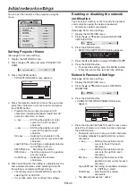
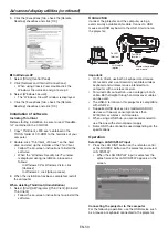
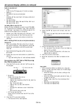
Setting or clearing DHCP Function

1.  Display the IP CONFIG menu.

2. Press the 

 or 

 button to select DHCP 

FUNCTION.

ON

DHCP FUNCTION

3. Press the 

 or 

 button select ON or OFF.

•  When DHCP FUNCTION is set to OFF, START 

IP ADDRESS and END IP ADDRESS cannot be 
set. If you want to set these settings, set DHCP 
FUNCTION to ON and perform the IP settings 
as follows.

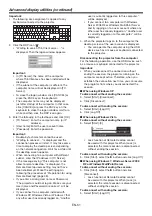
Start IP Address setting

1.  Display the IP CONFIG menu.

2. Press the 

 or 

 button to select START IP 

ADDRESS.

192. 168. 1. 11

START IP ADDRESS

3.  Press the ENTER button.

•  START IP ADDRESS screen appears.

START IP ADDRESS

192 . 168 .    1 .   11

0

OK

CLEAR

DEL

CANCEL

1

2

3

4

5

6

7

8

9

4.  Enter the Start IP address.

•  Refer to IP Address Settings for the detail of 

entering.

5.  When selecting OK, the setting is completed as 

the Start IP address stored temporarily. However, 
when selecting CANCEL, the setting is completed 
without storing.
•  Set the numeric value within the range from 0 to 

255. However, set the numeric value for the fi nal 
octet within the range from 2 to 254. Moreover, 
set the numeric value larger than IP address in 
the same subnet class.

•  When the setting you entered is correct, the 

IP CONFIG menu is displayed. If the entered 
content is not correct, the IP CONFIG menu is 
displayed after an error dialog is displayed.

•  Until the execution of SAVE SETTING, the 

change is not saved.

Initial network settings  (continued)

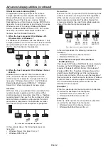
End IP Address setting

1.  Display the IP CONFIG menu.

2. Press the 

 or 

 button to select END IP 

ADDRESS.

192. 168. 1. 254

END IP ADDRESS

3.  Press the ENTER button.

•  END IP ADDRESS screen appears.

END IP ADDRESS

192 . 168 .    1 . 254

0

OK

CLEAR

DEL

CANCEL

1

2

3

4

5

6

7

8

9

4.  Enter the End IP address.

•  Refer to IP Address Settings for the detail of 

entering.

5.  When selecting OK, the setting is completed as 

the End IP address stored temporarily. However, 
when selecting CANCEL, the setting is completed 
without storing.
•  Set the numeric value within the range from 0 to 

255. However, set the numeric value for the fi nal 
octet within the range from 3 to 254. Moreover, 
set the numeric value larger than Start IP 
address in the same subnet class.

•  When the setting you entered is correct, the 

IP CONFIG menu is displayed. If the entered 
content is not correct, the IP CONFIG menu is 
displayed after an error dialog is displayed.

•  Until the execution of SAVE SETTING, the 

change is not saved.

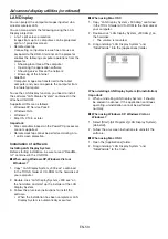
Saving IP CONFIG Settings

1.  Display the IP CONFIG menu.

2. Press the 

 button to select SAVE SETTING.

SAVE SETTINGS

OK

3.  Press the ENTER button.

•  The setting change dialog is displayed. After 

the dialog disappears, the NETWORK menu is 
displayed.

•  It may take some time to refl ect the settings.

Содержание DLP NW31U-EST

Страница 1: ...U NW31U EST This User Manual is important to you Please read it before using your projector DLP PROJECTOR MODEL NW31U EST User Manual...

Страница 2: ...OCK HAZARD DO NOT EXPOSE THIS APPLIANCE TO RAIN OR MOISTURE CAUTION TO PREVENT ELECTRIC SHOCK DO NOT USE THIS POLARIZED PLUG WITH AN EXTENSION CORD RECEPTACLE OR OTHER OUTLET UNLESS THE BLADES CAN BE...

Страница 3: ...Microsoft Corporation in the United States and or other countries Mac Mac OS OS X Finder and Apple Store are trademarks of Apple Inc Intel and Pentium are trademarks of Intel Corporation in the U S an...

Страница 4: ...ds Never push objects of any kind through openings of this projector as they may touch dangerous voltage points or short out parts that could result in a re or electric shock Never spill liquid of any...

Страница 5: ...r rises very high while the light source is illuminating Do not use the projector with condensation on it It can lead to breakdown or other failure Place of installation For safety s sake refrain from...

Страница 6: ...dispose of the batteries together with other conductive objects such as a metal piece they may short out resulting in re or explosion Batteries may explode if misused Do not recharge disassemble or he...

Страница 7: ...or 7 AUTO POSITION button 8 MENU button 9 AV MUTE button 10 VOLUME button 1 2 3 5 6 7 11 12 13 14 8 9 10 4 1 LAN terminal 2 USB A terminal 3 HDMI IN terminal HDMI 19 pin 4 COMPUTER COMPONENT VIDEO IN...

Страница 8: ...22 17 16 18 19 23 24 11 12 13 14 15 Remote control 1 ON button 2 COMPUTER 1 2 buttons 3 LAN DISP button 4 MENU button 5 ENTER button 6 3D button 7 KEYSTONE button 8 MAGNIFY button 9 E Z S E ZOOM SHIF...

Страница 9: ...pe of the screen used Reception angle horizontal About 30 About 30 About 30 About 30 Reception angle vertical About 40 About 30 About 5 About 5 Reception angle vertical ceiling mount About 40 About 30...

Страница 10: ...H Diagonal size Width W Height H Black space B inch cm inch cm inch cm inch cm inch cm inch cm inch cm inch m inch cm 70 178 56 142 42 107 66 168 56 142 35 89 3 5 9 20 0 52 4 4 11 80 203 64 163 48 122...

Страница 11: ...ced image 3 Press the ENTER button The E SHIFT menu appears at the center of the screen E SHIFT ENTER E ZOOM 4 Press the or button to move the projected image position Every time the button is pressed...

Страница 12: ...TITUDE MODE by pressing the or button HIGH ALTITUDE MODE STANDARD 3 Press the ENTER button HIGH ALTITUDE MODE HIGH ALTITUDE MODE STANDARD 4 Select STANDARD or HIGH ALTITUDE by pressing the or button 5...

Страница 13: ...takes effect the resolution decreases In addition stripes may appear or straight lines may bend in images with complicated patterns They are not due to product malfunctions When the KEYSTONE mode adj...

Страница 14: ...st 70 kgf When using metal wires secure one end to the adjustment foot of the projector and the other end to the mount kit In this case make sure that no electrical current is owing in the mount kit d...

Страница 15: ...ut L To audio output R To video output To S Video output Important Match the colors of the video and audio plugs on the Audio cable with those of the terminals Speaker output is mono Projector DVD pla...

Страница 16: ...ice such as a DVD player via the HDMI terminal black color may appear dark and deep depending on the type of the connected device This depends on the black level setting of the connected device There...

Страница 17: ...ors or analog RGB output adapters to be connected with this projector Contact your dealer for further information This projector uses stereo mini jack for its audio input Check the type of the audio o...

Страница 18: ...er cord If the power cord is modi ed or altered it may cause re or electric shock Caution Plug in the power cord rmly When unplugging hold and pull the power plug not the power cord Do not plug in or...

Страница 19: ...hown right appears Press the or button to select an input and press the ENTER button The projector automatically selects the appropriate signal format The selected signal format is displayed on the sc...

Страница 20: ...remote control or VOLUME button on the projector The volume control bar will appear on the screen Press the VOLUME or button while the volume control bar is displayed to adjust the volume The volume c...

Страница 21: ...The AUTO POWER OFF function does not work during AV MUTE AUTO POSITION button When the image supplied from the computer is displaced carry out the following procedure 1 Project a bright image containi...

Страница 22: ...768 16 9 04 1280 x 720 16 9 1280 x 720 16 10 960 x 720 16 9 6 1200 x 720 16 9 04 1280 x 720 16 9 1280 x 720 4 3 1066 x 800 16 9 6 1066 x 640 16 9 04 1066 x 602 16 9 1066 x 600 16 9 1280 x 720 16 10 16...

Страница 23: ...or Blu ray player 2 Display the IMAGE menu See page 26 for menu setting 3 Press the or button to select 3D 4 Press the or button to select ON 5 Press the ENTER button 3D 3D FORMAT AUTO 3D SYNC INVERT...

Страница 24: ...ses should not be used by children younger than 5 years old As young children do not show noticeable symptoms of fatigue or discomfort their physical condition may deteriorate suddenly When this produ...

Страница 25: ...TER INPUT AUTO OVER SCAN HOLD USER FINE SYNC SIGNAL VERT POSITION 0 MEMORY CALL RESOLUTION MEMORIZE AUTO HORIZ POSITION 0 TRACKING opt ENTER 0 1024 x 768 ON 60 00 Hz RESOLUTION 1024 x 768 VERTICAL FRE...

Страница 26: ...displayed in red letters 4 Press the or button to select an item to adjust IMAGE BRIGHTNESS 0 COLOR ENHANCER AUTO CONTRAST STANDARD COLOR TEMP 0 opt 5 Set the selected item by pressing the or button...

Страница 27: ...page 34 COLOR TEMP STANDARD LOW HIGH Select from the predetermined color temperatures USER Use to adjust the color temperature to a desired value See page 34 COLOR MANAGEMENT AUTO Select to use the p...

Страница 28: ...tion function displays text information included in the NTSC signal which is mainly used for TV broadcasting in North America INSTALLATION menu INSTALLATION SILENT MODE OFF LOW OFF STANDBY MODE IMAGE...

Страница 29: ...when viewing images projected from behind the screen with the projector installed on the oor INVERT Select when viewing images projected from behind the screen with the projector installed on the ceil...

Страница 30: ...urce signal is input Select AUTO for normal use OFF The lm mode will not be activated VIDEO SIGNAL AUTO NTSC PAL SECAM 4 43NTSC PAL M PAL N PAL 60 When AUTO is selected the appropriate video format is...

Страница 31: ...t the horizontal position of the projected image VERT POSITION 0 999 Use to adjust the vertical position of the projected image FINE SYNC 0 31 Use to eliminate ickering or blur if appears viewing the...

Страница 32: ...SK When DHCP is set to ON you cannot change this setting DEFAULT GATEWAY Press the ENTER button to set DEFAULT GATEWAY When DHCP is set to ON you cannot change this setting MAC ADDRESS xx xx xx xx xx...

Страница 33: ...Indicates the name of the terminal to which the currently projected video signal is being input RESOLUTION Indicates the resolution of the currently projected video signal VERTICAL FREQUENCY Indicate...

Страница 34: ...ton is pressed the color becomes thicker Every time the button is pressed the color becomes lighter TINT Use to adjust the tint of the projected image Every time the button is pressed the image appear...

Страница 35: ...e or button to select COLOR SYSTEM or GAMMA MODE 6 Press the or button to adjust the selected item COLOR SYSTEM Use this item to change the balance between the brightness and hue STANDARD Select when...

Страница 36: ...ENTER button 5 Press the or button to select a color to be adjusted RED GREEN BLUE CYAN YELLOW MAGENTA or WHITE 6 Press the or button to select an item to be adjusted GAIN SATURATION or HUE RED GREEN...

Страница 37: ...setting of your computer is different from the setting of RESOLUTION MEMORIZE in the SIGNAL menu of the projector Select RESOLUTION MEMORIZE in the SIGNAL menu and press the ENTER button Set HORIZ PIX...

Страница 38: ...the right or left half of the image Adjust SHUTTER LS or SHUTTER RS in the SIGNAL USER menu Noise appears on the top or bottom part of the image Adjust SHUTTER U or SHUTTER L in the SIGNAL USER menu...

Страница 39: ...AN adapter or by connecting to wireless router you can project images of the Microsoft PowerPoint Word Excel PDF or TXT format les stored in tablet computers or smartphones In some cases you can conne...

Страница 40: ...he display returns the NETWORK menu after selecting OK or CANCEL It may take some time to re ect the settings Enabling or disabling the network certification You can select whether or not to certify t...

Страница 41: ...select CANCEL the NETWORK menu is displayed without changing the password If the entered content is not matched NEW NETWORK PASSWORD screen appears again after an error dialog is displayed It may tak...

Страница 42: ...T MASK SUBNET MASK 255 255 255 0 3 Press the ENTER button SUBNET MASK screen appears SUBNET MASK 255 255 255 0 0 OK CLEAR DEL CANCEL 1 2 3 4 5 6 7 8 9 4 Enter the Subnet Mask Refer to IP Address Setti...

Страница 43: ...CONFIG menu is displayed after an error dialog is displayed Until the execution of SAVE SETTING the change is not saved Initial network settings continued End IP Address setting 1 Display the IP CONF...

Страница 44: ...NCEL to complete the setting without storing Initial network settings continued The display returns to the WIRELESS SETTING menu after selecting CANCEL Channel setting 1 Display the WIRELESS SETTING m...

Страница 45: ...4 If the ENTER button is pressed again the network settings will be initialized It may take some time to initialize the settings Restart of network function See page 26 for menu setting 1 Display the...

Страница 46: ...ially available USB wireless LAN adapter Tablet computer USB wireless LAN adapter option To USB A terminal Important Some USB wireless LAN adapters cannot be used depending on the speci cations Wirele...

Страница 47: ...ing its SSID 4 Select a le to be projected by tapping its name The image of the selected le is displayed 5 Operate the image by touching the tablet screen Flick the screen to move to the previous or n...

Страница 48: ...ng Remote Desktop The thin client function utilizes the standard Microsoft Remote Desktop function To use the Remote Desktop function perform the following preparations on the computer Important For t...

Страница 49: ...ed 6 Perform steps 7 10 in the section In Windows Vista Windows 7 Windows Server 2008 R2 or Windows MultiPoint Server 3 Configuration of Windows Firewall Con gure Windows Firewall as follows In Window...

Страница 50: ...structions to uninstall the software Connection Connect the projector and the computer using a commercially available LAN cable Connect a USB mouse and USB keyboard to the USB A terminal on the projec...

Страница 51: ...er name and Password are correct will be displayed If you connect to a computer installed with Windows XP Windows Vista or Windows 7 that any other user has already logged on Another user is currently...

Страница 52: ...le sites is smaller than that of the thin client computers or projectors E g when two users operate four devices In the example above the following licenses are necessary Windows Server CAL User CAL x...

Страница 53: ...re starting installation be sure to read ReadMe txt contained in the CD ROM When using Windows XP Windows Vista or Windows 7 1 Copy LAN Display System_v300 exe contained in the TOOLS folder of CD ROM...

Страница 54: ...em icon to execute the program The program starts to search for projectors automatically During searching for projectors Searching icon is displayed When a projector is found the computer logs in to t...

Страница 55: ...LAN Display System Important The items marked with are not available for Mac OS X When Advanced Screen Capture is enabled the computer mouse cursor may blink To send Audio to Display the Vertual Audio...

Страница 56: ...USB HID device with power consumption less than 5V 500mA When using a keyboard and mouse together we recommend a commercially available wireless keyboard and wireless mouse intended for a computer wit...

Страница 57: ...to install the software PtG Converter Lite contained in the attached CD ROM Important Supported USB Flash drive format is FAT32 Only one logical partition in USB Flash drive is supported Supported US...

Страница 58: ...ite 1 Click the PtG Converter Lite icon to execute the program PPT conversion button Menu bar Menu bar Right click to open the menu Output Resolution Selects the resolution of the PtG le after the con...

Страница 59: ...R button The Setup screen appears 3 Press the or button to select a setting item and press the or button to change the setting AutoRun Enables or disables the AutoRun and slideshow function AutoRun Sl...

Страница 60: ...older Important The AutoRun function supports single PtG le only The PtG le located on the top by sorting is played if multiple PtG les exists in AUTORUN folder 7 Connect the USB device to the USB A t...

Страница 61: ...changed In such cases press the ENTER button to cancel the password function and try again 4 Press the ENTER button The screen for setting the password function will appear FEATURE DISPLAY INPUT opt...

Страница 62: ...ion timer on the screen Presentation timer is available while viewing the image from the COMPUTER1 COMPUTER2 HDMI LAN DISPLAY or USB VIEWER input source To display the TIMER 1 Press the TIMER button o...

Страница 63: ...s operation using a personal computer via a LAN Major functions ProjectorView Global Batch projector controlling supervising application software Batch operation of stand alone projector multiple pro...

Страница 64: ...ching 11 COMPUTER1 12 COMPUTER2 21 VIDEO 22 S VIDEO 31 HDMI 41 USB VIEWER 51 LAN DISPLAY INPT Inquiry about input switching AVMT Mute control 30 Video and audio mute disable 31 Video and audio mute en...

Страница 65: ...or deteriorating Do not spray insecticide on or inside the projector Do not use benzine or thinner to clean it Do not let rubber or plastic materials contact with projector Cleaning of the lens Remove...

Страница 66: ...extension cable Check any object is not placed in front of Intelligent glare sensor Power turns off This problem may occur when the intake vent and or exhaust vents are blocked In such a case the STA...

Страница 67: ...n on projected images This symptom is normal for a DLP projector and is not a malfunction A very small number of pixels may stay lit or out but such symptom is not a malfunction Pixels of 99 99 or mor...

Страница 68: ...oling the inside of the projector You may feel hot but this is not a malfunction No audio is output Check that the volume isn t set to low Check the setting of AUDIO INPUT PROJECTION in the INSTALLATI...

Страница 69: ...screen Are you viewing images from a very close distance Viewing images from a very close distance may not obtain the 3D effect View images from a proper distance The 3D glasses may become out of sync...

Страница 70: ...eady green The power is on Normal condition Abnormal condition POWER STATUS CONDITION POSSIBLE SOLUTION Blinking green red Off Safety lock Unplug the power cord from the wall outlet and contact your d...

Страница 71: ...minal type Line Analog RGB Mini D SUB 15 pin 1 Audio output Terminal type Line Stereo mini jack 3 5 1 Speaker 10 W Mono Round type x 1 Control terminal others RS 232C D SUB 9 pin LAN RJ 45 USB Type A...

Страница 72: ...GA95 800 x 600 59 970 94 890 1066 x 800 SVGA120RB 800 x 600 76 302 119 972 1066 x 800 XGA60 1024 x 768 48 360 60 000 1066 x 800 XGA70 1024 x 768 56 480 60 000 1066 x 800 XGA75 1024 x 768 60 020 70 070...

Страница 73: ...A 75 1680 x 1050 82 306 74 892 1280 x 800 WSXGA 85 1680 x 1050 93 900 85 000 1280 x 800 WUXGA60RB 1920 x 1200 74 038 59 950 1280 x 800 WUXGA60 1920 x 1200 74 556 59 885 1280 x 800 1 FS Field Sequencia...

Страница 74: ...eld 3 TMDS Data 2 4 TMDS Data 1 5 TMDS Data1 Shield 6 TMDS Data 1 7 TMDS Data 0 8 TMDS Data 0 Shield 9 TMDS Data 0 10 TMDS Clock 11 TMDS Clock Shield 12 TMDS Clock 13 CEC 14 15 SCL 16 SDA 17 DDC Groun...

Страница 75: ...1 Zusho Baba Nagaokakyo City Kyoto Japan MITSUBISHIELECTRICCORPORATION A...

Отзывы: