


2-16
Installation
2Unpacking to Installation
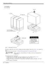
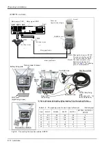
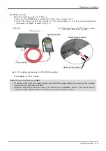
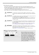
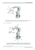
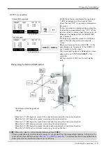
(2) CR751 controller
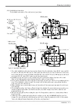
Fig.2-8 : Connecting the machine cables (CR751)
Fixing screws (2 places)
モータ信号ケーブル
モータ電源ケーブル
モータ信号(CN2)
CN2
固定ネジ
(2箇所)
モータ電源(CN1)
AMP1 AMP2 BRK
CN1
コントローラ前面
ロボット本体
(背面)
CONBOXカバー
固定ネジ
(2箇所)
Motor power cable
Motor signal cable
CONBOX cover
Robot arm
Opposite side of figure
Motor signal (CN2)
Motor power (CN1)
Controller
Two fixing screws
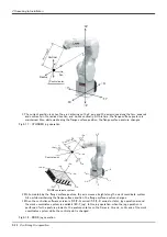
Note1) Although the figure is RV-4F/
7F series controller, and RV-
13F series is also the same.
Note2) The robot arm photo is for
illustrative purposes only.
Refer to
pose of actual products.
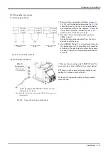
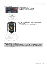
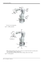
Pass into
the opening
AMP1
AMP2
CN2
Machine cables
Controller side
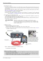
Battery fixing plate
Note1)
Note2)
CON cover
(Eight fixing screws)
Robot arm side
Cable clamp fixing
plate
(Two plate with
four screws each)
Two fixing screws
Connection condition
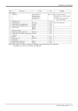
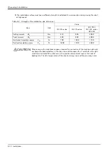
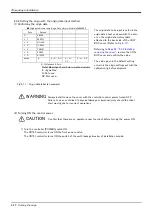
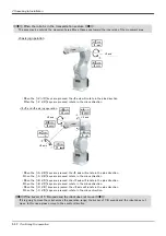
Table 2-3 : The packing pose for each type (reference)
(Unit: degree)
Axis
RV-4F
RV-4FL
RV-7F
RV-7FL
RV-7FLL, RV-13F/FL
RV-20F
J1
90
90
90
90
0
J2
-122
-121
-116
-115
-93
J3
162
165
158
164
160
J4
0
0
0
0
0
J5
45
41
48
41
23
J6
0
0
0
0
0
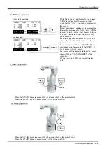
*1) Do not disconnect the battery cable connector. The origin data will be lost.
*2) The size of the cable clamp fixed plate fixed screw (four screws each) is M4x16.
*2)
Battery
cable
*1)
Содержание RV-13FM-SE Series
Страница 2: ......
Страница 138: ...Appendix 128 Configuration flag 6Appendix ...
Страница 139: ......


