3-64
Installing the solenoid valve set
3Installing the option devices
(2) RV-13F/13FL series, RV-20F
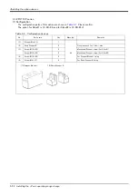
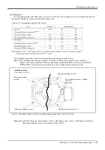
This paragraph explains how to install the solenoid valve set (1F-VD0*-03/1F-VD0*E-03) to RV-13F/13FL
series and RV-20F robots.
Turn the controller’s power OFF before this installing operation.
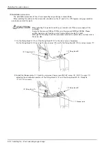
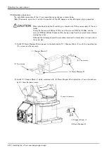
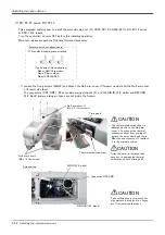
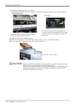
1) Loosen the four fixing screws of No.2 arm cover U (forearm upside) and remove the cover.
(Mounts the solenoid-valve set instead of the removed cover) The connectors (GR1, GR2) and air hoses (AIR
IN, RETURN) connected to the solenoid-valve set inside the cover.
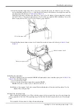
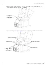
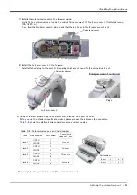
2) Connects the air hoses and the connectors.
a) Connects the hand output cable inside the forearm (GR1 and GR2) to the connectors of the solenoid-valve
set. Connect with the same names.
Note) In the solenoid-valve set of one set or two sets, connects only connector GR1.
b) The two air hoses equipped inside the forearm, connects AIR IN (white) to "P" port coupling of the sole
-
noid-valve set, and connects RETURN (black) to "R" port coupling of the solenoid-valve set. The AIR IN
(white) air hose is connected with the AIR IN coupling of the robot arm base rear, and the RETURN (black)
air hose is connected with the RETURN coupling.
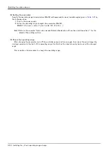
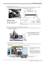
Because the long length air hoses are equipped, please cut and connect it to the
suitable length. If that is not right, the air hose breaks within the arm and it
becomes the cause that the solenoid valve operation is abnormal.
When connecting the RETURN air hose, be sure to remove the dust cap attached
at the RETURN coupling on the robot base section. If the cap is not removed,
exhaust air pressure will increase and the solenoid valve may not operate prop
-
erly. By connecting the exhaust air hose (φ6: customer preparation) to this
RETURN air coupling, exhaust air from the solenoid valve is able to escape to the
designated point.
No.2 arm cover U
Air hose:
AIR IN (white hose)
Air hose:
RETURN (black hose)
Connectors:
GR1, GR2
CAUTION
CAUTION
Connector: GR1
Connector: GR2
"P" port coupling
"R" port coupling
* The figure is an example of 1F-VD04-03.
Содержание RV-13FM-SE Series
Страница 2: ......
Страница 138: ...Appendix 128 Configuration flag 6Appendix ...
Страница 139: ......

