background image

6. SERVO MOTOR DRIVING 

6 -  31 


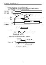
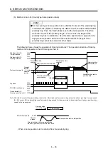
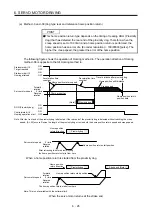
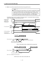
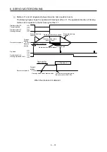
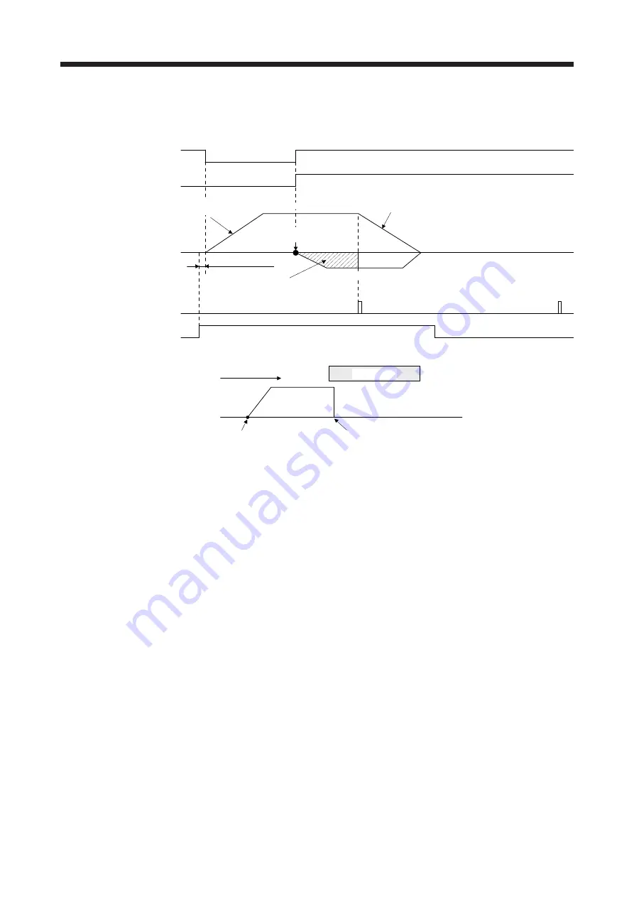
(j)  Method -11 and -43 (dogless Z-phase reference home position return) 

The following figure shows the operation of Homing method -11. The operation direction of Homing 
method -43 is opposite to that of Homing method -11. 

ON
OFF
ON
OFF

Controlword bit 4

Homing operation start

Creep speed

Servo motor speed

Reverse

rotation

0 r/min

Forward

rotation

Statusword bit 10

Target reached

ON
OFF

Statusword bit 12

Homing attained

ON
OFF

Z-phase

Acceleration time

constant

Deceleration time

constant

Home position shift distance

Home position return speed

Home position return

position data

10 ms or shorter


Servo motor speed

0 r/min

Forward

rotation

Home position return start position

Home position

return direction

The servo motor stops due to

the occurrence of [AL. 90].

Stroke end


When the stroke end is detected 


Содержание MELSERVO-JE

Страница 1: ...ut notice This Instruction Manual uses recycled paper MODEL MODEL CODE General Purpose AC Servo MR JE _C SERVO AMPLIFIER INSTRUCTION MANUAL PROFILE MODE HEAD OFFICE TOKYO BLDG MARUNOUCHI TOKYO 100 8310 MODEL MR JE _C SERVO AMPLIFIER INSTRUCTION MANUAL PROFILE MODE Ethernet Interface C C ...

Страница 2: ... or severe injury CAUTION Indicates that incorrect handling may cause hazardous conditions resulting in medium or slight injury to personnel or may cause physical damage Note that the CAUTION level may lead to a serious consequence according to conditions Please follow the instructions of both levels because they are important to personnel safety What must not be done and what must be done are ind...

Страница 3: ...g them directly or close to combustibles will lead to smoke or a fire Always connect a magnetic contactor between the power supply and the power supply L1 L2 L3 of the servo amplifier in order to configure a circuit that shuts down the power supply on the side of the servo amplifier s power supply If a magnetic contactor is not connected continuous flow of a large current may cause smoke or a fire...

Страница 4: ...Manual Do not get on or put heavy load on the product Otherwise it may cause injury The equipment must be installed in the specified direction Leave specified clearances between the servo amplifier and the cabinet walls or other equipment Do not install or operate the servo amplifier and servo motor which have been damaged or have any parts missing Do not block the intake and exhaust areas of the ...

Страница 5: ... connectors may be disconnected during operation Do not install a power capacitor surge killer or radio noise filter optional FR BIF on the servo amplifier output side To avoid a malfunction connect the wires to the correct phase terminals U V W of the servo amplifier and servo motor Connect the servo amplifier power output U V W to the servo motor power input U V W directly Do not let a magnetic ...

Страница 6: ...due to a collision Do not disassemble repair or modify the product Otherwise an electric shock fire injury etc may occur Disassembled repaired and or modified products are not covered under warranty Before resetting an alarm make sure that the run signal of the servo amplifier is off in order to prevent a sudden restart Otherwise it may cause an accident Use a noise filter etc to minimize the infl...

Страница 7: ...r Electromagnetic brake B RA Contacts must be opened with the emergency stop switch Contacts must be opened when ALM Malfunction or MBR Electromagnetic brake interlock turns off 24 V DC U To prevent an electric shock injury or fire from occurring after an earthquake or other natural disasters ensure safety by checking conditions such as the installation mounting wiring and equipment before switchi...

Страница 8: ...tion Manual SH NA 030257ENG MELSERVO JE Servo Amplifier Instruction Manual Troubleshooting SH NA 030166ENG MELSERVO MR JE _C Servo Amplifier Instruction Manual Positioning Mode SH NA 030277ENG MELSERVO MR JE _C Servo Amplifier Instruction Manual Network SH NA 030256ENG MELSERVO HG KN HG SN Servo Motor Instruction Manual SH NA 030135ENG MELSERVO EMC Installation Guidelines IB NA 67310ENG This Instr...

Страница 9: ...U S customary units are not shown in this manual Convert the values if necessary according to the following table Quantity SI metric unit U S customary unit Mass 1 kg 2 2046 lb Length 1 mm 0 03937 inch Torque 1 N m 141 6 oz inch Moment of inertia 1 10 4 kg m2 5 4675 oz inch2 Load thrust load axial load 1 N 0 2248 lbf Temperature N C 9 5 32 N F ...

Страница 10: ...tioning control parameters Pr PT_ _ 4 11 4 2 Detailed list of parameters 4 13 4 2 1 Basic setting parameters Pr PA_ _ 4 13 4 2 2 Extension setting parameters Pr PC_ _ 4 17 4 2 3 I O setting parameters Pr PD_ _ 4 19 4 2 4 Extension setting 2 parameters Pr PE_ _ 4 21 4 2 5 Positioning control parameters Pr PT_ _ 4 23 4 3 Software limit 4 30 4 4 How to set the electronic gear 4 30 4 4 1 Electronic ge...

Страница 11: ...iption 6 32 6 2 2 Related objects registers 6 32 6 2 3 Directions for use 6 35 6 3 Profile velocity mode pv 6 36 6 3 1 Function description 6 36 6 3 2 Related objects registers 6 36 6 3 3 Directions for use 6 39 6 4 Profile torque mode tq 6 41 6 4 1 Function description 6 41 6 4 2 Related objects registers 6 41 6 4 3 Directions for use 6 43 7 APPLICATION OF FUNCTIONS 7 1 to 7 2 7 1 Infinite feed f...

Страница 12: ...ollowing table are the same with the contents of MR JE _C Servo Amplifier Instruction Manual For details refer to each section indicated in the detailed explanation field MR JE _C means MR JE _C Servo Amplifier Instruction Manual Item Detailed explanation Combinations of servo amplifiers and servo motors MR JE _C section 1 4 Function list MR JE _C section 1 5 Model designation MR JE _C section 1 6...

Страница 13: ...n starts from the front end of the proximity dog After the rear end is passed the position is shifted by the travel distance after proximity dog and the home position shift distance The position after the shifts is set as the home position If the stroke end is detected during home position return the direction of movement is reversed Count type Front end detection front end reference Deceleration ...

Страница 14: ...lse method 22 Although this type is the same as the dog cradle type home position return the stop position is not on the Z phase Starting from the front end of the dog the position is shifted by the travel distance after proximity dog and the home position shift distance The position after the shifts is set as the home position If the stroke end is detected during home position return AL 90 Home p...

Страница 15: ...1 FUNCTIONS AND CONFIGURATION 1 4 MEMO ...

Страница 16: ...y and securely Otherwise the servo motor may operate unexpectedly resulting in injury Connect cables to the correct terminals Otherwise a burst damage etc may occur Ensure that polarity is correct Otherwise a burst damage etc may occur The surge absorbing diode installed to the DC relay for control output should be fitted in the specified direction Otherwise the converter unit and the drive unit w...

Страница 17: ...vo amplifier may cause a malfunction Before wiring switch operation etc eliminate static electricity Otherwise it may cause a malfunction The items shown in the following table are the same with the contents of MR JE _C Servo Amplifier Instruction Manual For details refer to each section indicated in the detailed explanation field MR JE _C means MR JE _C Servo Amplifier Instruction Manual Item Det...

Страница 18: ...MR JE _C Servo Amplifier Instruction Manual that gives the current value necessary for the interface The illustration of the 24 V DC power supply is divided between input signal and output signal for convenience However they can be configured by one 5 When starting operation always turn on EM2 Forced stop 2 LSP Forward rotation stroke end and LSN Reverse rotation stroke end normally closed contact...

Страница 19: ... 21 I Note 3 PD19 22 O INP PD32 23 LG 24 O LAR 25 O LBR 26 O LZR Note 1 I input signal O output signal 2 pp Profile position mode pv Profile velocity mode tq Profile torque mode 3 Input devices are not assigned by default Assign the input devices with Pr PD16 and Pr PD19 as necessary 4 Input devices are not assigned by default When using CN3 19 pin as the input device of sink interface assign the ...

Страница 20: ... input can be used For details of the touch probe function refer to MR JE _C Servo Amplifier Instruction Manual Network DI 1 2 4 Power on sequence POINT The output signal etc may be unstable at power on 1 Power on procedure 1 Always wire the power supply as shown in above section 3 1 of MR JE _C Servo Amplifier Instruction Manual using the magnetic contactor with the power supply L1 L2 L3 Configur...

Страница 21: ...2 SIGNALS AND WIRING 2 6 MEMO ...

Страница 22: ...ready AL 25 can be deactivated by cycling the power Also if the power is switched on when the servo motor is rotated at a speed of 3000 r min or higher a position mismatch may occur due to external force or the like Power must therefore be switched on when the servo motor is at a stop 2 Parameter setting POINT The following encoder cables are of four wire type When using any of these encoder cable...

Страница 23: ...o motor to a stop Quick stop command The servo motor decelerates to a stop Error occurrence Note 1 The servo motor decelerates to a stop Servo amplifier Alarm occurrence The servo motor decelerates to a stop With some alarms however the dynamic brake operates to stop the servo motor Note 2 EM2 Forced stop 2 off The servo motor decelerates to a stop AL E6 Servo forced stop warning occurs In the tor...

Страница 24: ...the controller make sure that the identification No of the servo amplifier is set correctly Otherwise the parameter settings of another identification No may be written possibly causing the servo amplifier to be an unexpected condition 4 1 Parameter list POINT To enable a parameter whose symbol is preceded by cycle the power after setting it However the time will be longer depending on a setting v...

Страница 25: ...C PA09 RSP Auto tuning response 16 PA10 INP In position range 100 pulse Section 4 2 1 PA11 TLP Forward rotation torque limit 1000 0 PA12 TLN Reverse rotation torque limit 1000 0 PA13 PLSS Command pulse input form 0100h MR JE _C PA14 POL Rotation direction selection 0 Section 4 2 1 PA15 ENR Encoder output pulses 4000 pulse rev MR JE _C PA16 ENR2 Encoder output pulses 2 1 PA17 For manufacturer setti...

Страница 26: ... Resonance frequency 100 0 Hz PB21 VRF13 Vibration suppression control 1 Vibration frequency damping 0 00 PB22 VRF14 Vibration suppression control 1 Resonance frequency damping 0 00 PB23 VFBF Low pass filter selection 0100h PB24 MVS Slight vibration suppression control 0000h PB25 BOP1 Function selection B 1 0000h PB26 CDP Gain switching function 0000h PB27 CDL Gain switching condition 10 kpulse s ...

Страница 27: ...on suppression control 2 Vibration frequency damping 0 00 PB55 VRF24 Vibration suppression control 2 Resonance frequency damping 0 00 PB56 VRF21B Vibration suppression control 2 Vibration frequency after gain switching 0 0 Hz PB57 VRF22B Vibration suppression control 2 Resonance frequency after gain switching 0 0 Hz PB58 VRF23B Vibration suppression control 2 Vibration frequency damping after gain...

Страница 28: ...02 STB Deceleration time constant 0 ms PC03 STC S pattern acceleration deceleration time constant 0 ms MR JE _C PC04 TQC Torque command time constant 0 ms PC05 SC1 Internal speed command 1 100 00 r min Internal speed limit 1 PC06 SC2 Internal speed command 2 500 00 r min Internal speed limit 2 PC07 SC3 Internal speed command 3 1000 00 r min Internal speed limit 3 PC08 SC4 Internal speed command 4 ...

Страница 29: ...nufacturer setting 0000h PC37 VCO Analog speed command offset 0 mV PC38 TPO Analog torque command offset 0 mV Analog torque limit offset PC39 For manufacturer setting 0 PC40 0 PC41 0 PC42 0 PC43 ERZ Error excessive alarm detection level 0 rev PC44 For manufacturer setting 0000h PC45 0000h PC46 0 PC47 0 PC48 0 PC49 0 PC50 0000h PC51 RSBR Forced stop deceleration time constant 100 ms PC52 For manufa...

Страница 30: ...ection 7M Pr PD26 Input device selection 8L Pr PD27 Input device selection 8M No Symbol Name Initial value Unit Detailed explanation PD01 DIA1 Input signal automatic on selection 1 0000h MR JE _C PD02 For manufacturer setting 0000h PD03 0000h PD04 0000h PD05 DI1L Input device selection 1L 0202h PD06 DI1M Input device selection 1M 0202h PD07 DI1H Input device selection 1H 002Bh Section 4 2 3 PD08 D...

Страница 31: ...er setting 0000h MR JE _C PD34 DIF Input filter setting 0004h PD35 DOP1 Function selection D 1 0101h Section 4 2 3 PD36 For manufacturer setting 0000h MR JE _C PD37 DOP3 Function selection D 3 0000h PD38 DOP4 Function selection D 4 3000h Section 4 2 3 PD39 DOP5 Function selection D 5 0000h MR JE _C PD40 For manufacturer setting 0000h PD41 TPOP Touch probe function selection 0000h Section 4 2 3 PD4...

Страница 32: ...LMCP Lost motion compensation positive side compensation value selection 0 0 01 Section 4 2 4 PE45 LMCN Lost motion compensation negative side compensation value selection 0 0 01 PE46 LMFLT Lost motion filter setting 0 0 1 ms PE47 TOF Torque offset 0 0 01 PE48 LMOP Lost motion compensation function selection 0000h PE49 LMCD Lost motion compensation timing 0 0 1 ms PE50 LMCT Lost motion compensatio...

Страница 33: ...00h PF21 DRT Drive recorder switching time setting 0 s PF22 For manufacturer setting 200 PF23 OSCL1 Vibration tough drive Oscillation detection level 50 PF24 OSCL2 Vibration tough drive function selection 0000h PF25 CVAT Instantaneous power failure tough drive Detection time 200 ms PF26 For manufacturer setting 0 PF27 0 PF28 0 PF29 0000h PF30 0 PF31 FRIC Machine diagnosis function Friction judgmen...

Страница 34: ...r time 100 ms PT11 ZTT Stopper type home position return torque limit value 15 0 PT12 For manufacturer setting 0 PT13 100 00 PT14 0 PT15 LMPL Software limit 0000h 10 3 degree pulse Section 4 2 5 PT16 LMPH 0000h 10 3 degree pulse PT17 LMNL Software limit 0000h 10 3 degree pulse PT18 LMNH 0000h 10 3 degree pulse PT19 For manufacturer setting 0000h PT20 0000h PT21 0000h PT22 0000h PT23 0 PT24 0 PT25 ...

Страница 35: ...rer setting 0 PT59 DCTH Travel distance after proximity dog extension parameter 0 10 3 degree pulse Section 4 2 5 PT60 TOP8 Function selection T 8 0000h PT61 HMA Home position return acceleration time constant 0 ms PT62 HMB Home position return deceleration time constant 0 ms PT63 ZSP2L Zero speed 2 level 50 00 r min PT64 ZSP2F Zero speed 2 filtering time 10 ms PT65 INP2R In position 2 output rang...

Страница 36: ...mode and speed control mode P S 2 Speed control mode S 3 Speed control mode and torque control mode S T 4 Torque control mode T 5 Torque control mode and position control mode T P 6 Positioning mode point table method CP 8 Positioning mode indexer method PS 9 Profile mode pp pv tq 0h _ _ x _ For manufacturer setting 0h _ x _ _ 0h x _ _ _ 1h PA03 ABS Absolute position detection system _ _ _ x Absol...

Страница 37: ... servo motor resolution 131072 pulses rev Be sure to set the electronic gear with servo off state to prevent unexpected operation due to improper setting This parameter corresponds to Motor revolutions Index 6091h Sub 1 When this parameter is mapped to the link device of CC Link IE Field Network Basic the value written with MR Configurator2 is overwritten by the controller Thus do not write a valu...

Страница 38: ...th MR Configurator2 is overwritten by the controller Thus do not write a value with MR Configurator2 Setting range 0 0 to 1000 0 1000 0 PA12 TLN Reverse rotation torque limit You can limit the torque generated by the servo motor Set the parameter on the assumption that the rated torque is 100 0 Set this parameter when limiting the torque of the servo motor in the CW power running or CCW regenerati...

Страница 39: ...rofile torque mode Setting value Servo motor rotation direction Pr PA14 Pr PC29 Torque mode Torque command Forward Torque mode Torque command Reverse 0 0 _ _ _ Enabled CCW CW 1 _ _ _ Disabled CCW CW 1 0 _ _ _ Enabled CW CCW 1 _ _ _ Disabled CCW CW The following shows the servo motor rotation directions Forward rotation CCW Reverse rotation CW Setting range 0 1 PA21 AOP3 Function selection A 3 _ _ ...

Страница 40: ... value written with MR Configurator2 is overwritten by the controller Thus do not write a value with MR Configurator2 Setting range 0 to 50000 0 ms PC02 STB Deceleration time constant Set the deceleration time taken from the rated speed to 0 r min for the command Set the deceleration time constant in the profile position mode and the profile velocity mode Setting a value exceeding 20000 ms in the ...

Страница 41: ...r digits Set a following error output level Upper and lower are a set This function will be enabled in the profile position mode When the state in which the value of droop pulses exceeds the setting value for Pr PC75 Pr PC76 continues for the time set in Pr PC77 or longer Statusword Index 6041h bit 13 Following error will be turned on However setting FFFFFFFFh will disable it Set a value in hexade...

Страница 42: ...to table 4 1 for settings 2Bh _ x _ _ For manufacturer setting 0h x _ _ _ 0h Table 4 1 Selectable input devices Setting value Input device 04 PC Proportional control 0A LSP Forward rotation stroke end 0B LSN Reverse rotation stroke end 0D CDP Gain switching 2B DOG Proximity dog 2C TPR1 touch probe 1 Note Note This can be used when TRP1 is assigned to CN3 6 with Pr PD25 Input device selection 7H PD...

Страница 43: ..._ _ 0 4 INP In position _ _ 0 5 MBR Electromagnetic brake interlock _ _ 0 7 TLC Limiting torque _ _ 0 8 WNG Warning _ _ 0 9 BWNG Battery warning _ _ 0 A SA Speed reached _ _ 0 B VLC Limiting speed _ _ 0 C ZSP Zero speed detection _ _ 0 D MTTR During tough drive _ _ 0 F CDPS Variable gain selection _ _ 1 1 ABSV Absolute position undetermined PD30 DO2 Output device selection 2 _ _ x x Device selecti...

Страница 44: ... pin the OP is outputted regardless of the setting in Pr PD29 0 Not assigned 1 CN3 14 Pr PD29 disabled 2 CN3 15 Pr PD30 disabled 3 CN3 16 Pr PD31 disabled 4 CN3 22 Pr PD32 disabled 3h PD41 TPOP Touch probe function selection _ _ _ x For manufacturer setting 0h _ _ x _ Touch probe signal filter selection 0 Not assigned 1 0 111 ms 2 0 222 ms 3 0 444 ms 0h _ x _ _ For manufacturer setting 0h x _ _ _ ...

Страница 45: ... torque offset in the torque control mode Setting range 10000 to 10000 0 0 01 PE48 LMOP Lost motion compensation function selection _ _ _ x Lost motion compensation selection 0 Disabled 1 Enabled This function will be enabled in the profile position mode 0h _ _ x _ Unit setting of lost motion compensation non sensitive band 0 1 pulse unit 1 1 kpulse unit This function will be enabled in the profil...

Страница 46: ...e with MR Configurator2 100 00 r min PT06 CRF Creep speed Set a creep speed after proximity dog at home position return Setting range 0 to instantaneous permissible speed This parameter corresponds to Speed during search for zero Index 6099h Sub 2 When this parameter is mapped to the link device of CC Link IE Field Network Basic the value written with MR Configurator2 is overwritten by the control...

Страница 47: ...Upper four digits Lower four digits Pr PT15 Pr PT16 Setting an identical value for Software limit and this parameter will disable the software limit Refer to section 4 3 When changing the setting with the parameter change it during servo off in the homing mode velocity mode or torque mode In the position mode during servo on changing the setting in a certain order may trigger AL 35 AL 69 or AL 98 ...

Страница 48: ...to the link device of CC Link IE Field Network Basic the value written with MR Configurator2 is overwritten by the controller Thus do not write a value with MR Configurator2 Setting range 00000000h to FFFFFFFFh 0000h Refer to Function column for unit PT18 LMNH Software limit upper four digits 0000h Refer to Function column for unit PT26 TOP2 Function selection T 2 _ _ _ x Electronic gear fraction ...

Страница 49: ...ue with MR Configurator2 37 Setting value Home position return direction Home position return method Setting value Home position return direction Home position return method 1 Address increasing direction Dog type 33 Address decreasing direction Dog type rear end detection Z phase reference rear end detection Z phase reference 2 Count type 34 Count type front end detection Z phase reference front ...

Страница 50: ...the controller Thus do not write a value with MR Configurator2 Setting range 0 0 to 1000000 0 0 0 s PT50 PVC Profile speed command Set the speed of the profile speed command The fractional portion of the parameter will be rounded down This function will be enabled in the profile position mode This parameter corresponds to Profile velocity Index 6081h When this parameter is mapped to the link devic...

Страница 51: ... rated speed This function will be enabled in the profile mode When Using Pr PT61 as deceleration time constant _ _ _ 0 is selected in Home position return Deceleration time constant selection of Pr PT60 the value set in this parameter is used as a deceleration time constant at home position return This parameter corresponds to Homing acceleration Index 609Ah When this parameter is mapped to the l...

Страница 52: ...Pr PT65 In position 2 output range continues for the time set in this parameter or longer Statusword Index 6041h bit 10 Target reached will be turned on However when this parameter is set to 65535 Statusword Index 6041h bit 10 Target reached will be always on This function will be enabled in the profile position mode and homing mode This parameter corresponds to Position window time Index 6068h Wh...

Страница 53: ...ravel possible 4 4 How to set the electronic gear 4 4 1 Electronic gear setting for the profile mode 1 Setting pulse with Position data unit of Pr PT01 Adjust Pr PA06 and Pr PA07 to match the servo amplifier setting with the travel distance of the machine Travel distance CDV CMX Deviation counter Electronic gear Pr PA06 Pr PA07 Servo motor Encoder M Pt Servo motor encoder resolution 131072 pulse r...

Страница 54: ...pulse α is 1 Therefore set CMX 131072 and CDV 5 b Setting example of a conveyor Machine specifications Pulley diameter r 160 mm Reduction ratio 1 n Z1 Z2 1 3 Z1 Number of gear teeth on servo motor side Z2 Number of gear teeth on load side Servo motor encoder resolution 131072 pulse rev Z1 Z2 1 n Z1 Z2 1 3 1 n r 160 mm Servo motor encoder resolution Pt 131072 pulse rev CMX CDV Pt ΔS Pt 1 n r π α No...

Страница 55: ...e will trigger AL 37 Parameter error a Set values to make numerator and denominator 16384 or lower if the electronic gear CMX CDV is reduced to its lowest terms b Set values to make numerator and denominator 16777216 or lower if CMX Pt CDV 360000 is reduced to its lowest terms The following shows a setting example of the electronic gear Number of gear teeth on machine side 25 number of gear teeth ...

Страница 56: ..._ _ 9 Profile mode Servo on SON Reset RES Control switching LOP Forward rotation start reverse rotation selection ST1 RS2 Reverse rotation start forward rotation selection ST2 RS1 4 5 2 Restrictions on objects registers The following objects registers can be used when Pr PA01 _ _ _ 9 Profile mode They cannot be used when Pr PA01 _ _ _ 0 to _ _ _ 5 Position speed torque control mode objects registe...

Страница 57: ...4 PARAMETERS 4 34 MEMO ...

Страница 58: ...etails of the objects registers refer to MR JE _C Servo Amplifier Instruction Manual Network Function Description Detailed explanation State machine control of the servo amplifier The controller can control the state machine of the servo amplifier to drive the servo motor Section 5 1 Control mode The profile mode can be selected Section 5 2 Homing mode This is a mode where the servo amplifier perf...

Страница 59: ...d Ready off Servo off During main circuit charging Ready on Servo on 9 8 12 11 16 H Fault Error occurs Transition by slave Transition by master Transition by slave or master 10 2 0 1 7 15 3 6 4 5 G Fault reaction active Servo initialization in process In wait for forced stop reset Forced stop deceleration Occurrence of alarm In normal drive servo on Alarm handling in process forced stop decelerati...

Страница 60: ... transitions with the Disable Voltage command from the master Operation is disabled after servo off or RA off 10 The state transitions with the Disable Voltage command or Quick Stop command from the master RA turns off 11 The state transitions with the Quick Stop command from the master Quick Stop starts 12 a The state automatically transitions after Quick Stop is completed If the Quick Stop optio...

Страница 61: ...p 9 Operation Mode Specific Differs depending on Modes of operation 6060h Refer to chapter 6 10 to 14 Reserved The value at reading is undefined Set 0 when writing 15 New set point 0 The servo motor is stopped 1 The servo motor is driven This is used in the profile velocity mode Refer to section 6 3 2 Note 1 The description changes depending on the control mode 2 The value at reading is undefined ...

Страница 62: ...nding on Modes of operation 6060h Refer to chapter 6 11 ILA Internal limit active 0 The forward rotation stroke end reverse rotation stroke end and software position limit have not been reached 1 The forward rotation stroke end reverse rotation stroke end or software position limit has been reached Enabled in the pp pv or hm mode 12 to 13 OMS Operation Mode Specific Differs depending on Modes of o...

Страница 63: ...enabled x0xx xxx0 x00x 0111 Quick stop active x0xx xxx0 x0xx 1111 Fault reaction active x0xx xxx0 x0xx 1000 Fault Note Statusword is not sent in the Not ready to switch on state 5 1 3 Directions for use A control command allows a transition to the target status skipping the statuses in between The statuses can transition as shown in the following table for example Refer to the figure in section 5 ...

Страница 64: ...le lists the control switching conditions of the profile mode Switching operation Switching condition 1 Profile position mode Profile velocity mode While the servo motor is stopped Note 1 2 Profile velocity mode Profile position mode 3 Profile position mode Profile torque mode 4 Profile torque mode Profile position mode 5 Profile velocity mode Profile torque mode Not restricted Note 2 6 Profile to...

Страница 65: ...DRIVE PROFILE 5 8 5 2 2 Related objects registers Index Sub Index Access Name Data Type Default 6060h 0 rw Modes of operation I8 0 6061h 0 ro Modes of operation display I8 20 6502h 0 ro Supported Drive Modes U32 ...

Страница 66: ...cation 6 1 1 Function description Perform a home position return operation following the instruction below For specified home position return operation set Homing method 6098h Homing speed 6099h and Homing acceleration 609Ah and then start the operation with Controlword 6040h The completion of the home position return operation can be checked with Statusword 6041h Controlword 6040h Homing accelera...

Страница 67: ...he home position after dog detection Note 1 Unit Vel unit 0 01 r min Range 0 to servo motor maximum speed 609Ah 0 rw Homing acceleration U32 0 Acceleration deceleration time constant at home position return Unit ms 60E3h 0 ro Supported Homing Method U8 40 Note 3 Number of entries of the supported home position return method 1 ro 1st supported homing method I8 37 The home position return method tha...

Страница 68: ...e value at reading is undefined Set 0 when writing To start a home position return operation turn bit 4 from 0 to 1 When the home position return operation is completed or an alarm is issued during the operation turn bit 4 from 1 to 0 When bit 8 Halt of the Controlword 6040h is set to 1 the servo motor decelerates to a stop After that when bit 8 Halt is set to 0 and bit 4 is turned to 0 and then 1...

Страница 69: ...d rotation Same as the dog type front end reference home position return Note that if the stroke end is detected during home position return AL 90 Home position return incomplete warning occurs 20 Homing without index pulse Forward rotation Although this type is the same as the dog cradle type home position return the stop position is not on the Z phase Starting from the front end of the dog the p...

Страница 70: ... position 33 Homing on index pulse Reverse rotation Although this type is the same as the dogless Z phase reference home position return the creep speed is applied as the movement start speed 34 Homing on index pulse Forward rotation Although this type is the same as the dogless Z phase reference home position return the creep speed is applied as the movement start speed 35 Homing on current posit...

Страница 71: ...osition return the direction of movement is reversed 38 Reverse rotation 7 Count type Front end detection front end reference Forward rotation Deceleration starts from the front end of the proximity dog The position is shifted by the travel distance after proximity dog and the home position shift distance The position after the shifts is set as the home position If the stroke end is detected durin...

Страница 72: ...ed successfully unless 0 is set in Bit 12 The following shows the conditions when 0 is set in Bit 12 For incremental system At power on At communication shut off by controller reset At home position return start At home position erasure For absolute position detection system At home position return start At home position erasure To check the home position return status with Statusword 6041h note t...

Страница 73: ... a command is input again bit 10 turns off 0 b Bit 12 Homing attained of Statusword 6041h Bit 12 turns off 0 when a home position return operation is started and turns on 1 when the operation is completed For absolute position detection system bit 12 turns on 1 after the power supply is turned on c Bit 13 Homing error of Statusword 6041h Bit 13 turns on 1 when an alarm or warning AL 90 2 AL 90 3 A...

Страница 74: ...t 12 Homing attained of Statusword 6041h turns on 1 Confirm the switching to Homing mode hm on Modes of operation display 6061h Save the parameter in the EEP ROM with Save application parameters of Store Parameters 1010h Set 1Fh in Controlword 6040h to start home position return Save the parameter in the EEP ROM with Save manufacturer defined parameters of Store Parameters 1010h Skip if the settin...

Страница 75: ...e last Z phase reference home position return and Method 4 has the operation of the dog cradle type home position return at a forward rotation start However if the stroke end is detected during home position return AL 90 occurs 3 3 4 4 Index Pulse Home Switch 2 Method 5 and 6 Homing on negative home switch and index pulse These home position return types use the front end of the proximity dog as r...

Страница 76: ...itch Positive Limit Switch 4 Method 17 to 30 Homing without index pulse Method 17 to 30 have the operation of Method 1 to Method 14 however these types set the home position not on the Z phase but on the dog Method 17 to 30 have the operation of Method 1 to Method 14 however these types set the home position not on the Z phase but on the dog The following figure shows the operation of the home pos...

Страница 77: ...ex Pulse 33 34 6 Method 35 and 37 Homing on current position These home position return types set the current position as a home position The operation is the same as that of the data set type home position return however these types can be executed even during servo off ON OFF ON OFF ON OFF Servo motor speed Statusword bit 10 Target reached Statusword bit 12 Homing attained Controlword bit 4 Homi...

Страница 78: ... Statusword bit 12 Homing attained ON OFF ON OFF Controlword bit 4 Homing operation start Home position return speed Deceleration time constant Home position shift distance Home position return position data ON OFF Proximity dog Creep speed Z phase DOG Proximity dog Acceleration time constant Home position return direction Home position return start position After retracting to before proximity do...

Страница 79: ...min Forward rotation Statusword bit 10 Target reached ON OFF ON OFF Statusword bit 12 Homing attained ON OFF ON OFF Controlword bit 4 Homing operation start ON OFF Z phase DOG Proximity dog Acceleration time constant Servo motor speed Reverse rotation 0 r min Forward rotation Home position return direction Home position return start position Home position shift distance Home position return positi...

Страница 80: ...ance Home position return position data ON OFF Proximity dog Creep speed Z phase DOG Proximity dog Acceleration time constant 10 ms or shorter Servo motor speed Reverse rotation 0 r min Home position return direction Home position return start position After retracting to before proximity dog the home position return starts from here Proximity dog When a home position return is started from the pr...

Страница 81: ... ON OFF ON OFF Controlword bit 4 Homing operation start ON OFF Z phase DOG Proximity dog Acceleration time constant 10 ms or shorter Servo motor speed Reverse rotation 0 r min Forward rotation Home position return direction Home position return start position Home position shift distance Home position return position data Proximity dog When a home position return is started from the proximity dog ...

Страница 82: ...d rotation Statusword bit 10 Target reached ON OFF Statusword bit 12 Homing attained ON OFF Controlword bit 4 Homing operation start DOG Proximity dog Acceleration time constant 10 ms or shorter Servo motor speed Reverse rotation 0 r min Home position return direction Home position return start position After retracting to before proximity dog the home position return starts from here Proximity do...

Страница 83: ...ached ON OFF ON OFF Statusword bit 12 Homing attained ON OFF ON OFF Controlword bit 4 Homing operation start ON OFF Z phase DOG Proximity dog Acceleration time constant 10 ms or shorter Servo motor speed Reverse rotation 0 r min Forward rotation Home position return direction Home position return start position Home position shift distance Travel distance after proximity dog Home position return p...

Страница 84: ...N OFF Statusword bit 12 Homing attained ON OFF Controlword bit 4 Homing operation start DOG Proximity dog Acceleration time constant 10 ms or shorter Servo motor speed Reverse rotation 0 r min Home position return direction Home position return start position After retracting to before proximity dog the home position return starts from here Proximity dog When a home position return is started from...

Страница 85: ...OFF ON OFF Controlword bit 4 Homing operation start ON OFF Z phase DOG Proximity dog Acceleration time constant 10 ms or shorter Servo motor speed Reverse rotation 0 r min Forward rotation Home position return direction Home position return start position Home position shift distance Travel distance after proximity dog Home position return position data Proximity dog When a home position return is...

Страница 86: ...bit 12 Homing attained ON OFF Z phase Acceleration time constant 10 ms or shorter Servo motor speed 0 r min Forward rotation Home position return start position Home position return direction The servo motor stops due to the occurrence of AL 90 Stroke end When the stroke end is detected 10 Method 35 and Method 37 Homing on current position The following figure shows the operation of Homing method ...

Страница 87: ...e DOG Proximity dog Acceleration time constant 10 ms or shorter Note After the front end of the proximity dog is detected if the distance after proximity dog is traveled without reaching the creep speed AL 90 occurs Set the travel distance after proximity dog enough for the servo motor to decelerate from the home position return speed to the creep speed Servo motor speed Reverse rotation 0 r min H...

Страница 88: ...roximity dog Note Deceleration time constant Home position return position data Servo motor speed Reverse rotation 0 r min Forward rotation Statusword bit 10 Target reached ON OFF ON OFF Statusword bit 12 Homing attained ON OFF ON OFF Controlword bit 4 Homing operation start ON OFF Z phase DOG Proximity dog Acceleration time constant Travel distance after proximity dog Home position shift distance...

Страница 89: ...ble with the software limit When the servo motor returns at the stroke end c Method 3 Data set type home position return The following figure shows the operation of Homing method 3 This type cannot be executed during servo off ON OFF ON OFF ON OFF Servo motor speed Statusword bit 10 Target reached Statusword bit 12 Homing attained Controlword bit 4 Homing operation start Home position return posit...

Страница 90: ... position return position data 10 ms or shorter 5 ms or longer ON OFF TLC Limiting torque Torque limit value Torque limit value Note 1 Pr PT11 Torque limit value Note 1 Note 2 Stopper time Pr PT10 Reverse rotation 0 r min Forward rotation Stopper Note 1 When Method 4 is set the torque limit value of Positive torque limit value 60E0h is applied When Method 36 is set the torque limit value of Negati...

Страница 91: ... Forward rotation Statusword bit 10 Target reached ON OFF ON OFF Statusword bit 12 Homing attained ON OFF ON OFF Controlword bit 4 Homing operation start DOG Proximity dog Acceleration time constant 10 ms or shorter Note After the front end of the proximity dog is detected if the rear end of the proximity dog is detected without reaching the creep speed AL 90 occurs Revise the length of the proxim...

Страница 92: ...on return position data Servo motor speed Reverse rotation 0 r min Forward rotation Statusword bit 10 Target reached ON OFF ON OFF Statusword bit 12 Homing attained ON OFF ON OFF Controlword bit 4 Homing operation start DOG Proximity dog Acceleration time constant Travel distance after proximity dog Home position shift distance 10 ms or shorter Servo motor speed Reverse rotation 0 r min Home posit...

Страница 93: ...ming attained ON OFF ON OFF Controlword bit 4 Homing operation start ON OFF Z phase DOG Proximity dog Acceleration time constant Servo motor speed Reverse rotation 0 r min Forward rotation Home position return direction Home position return start position Home position shift distance Home position return position data Proximity dog When a home position return is started from the proximity dog Serv...

Страница 94: ...G Proximity dog 10 ms or shorter Note After the front end of the proximity dog is detected if the rear end of the proximity dog is detected without stop AL 90 occurs Revise the length of the proximity dog or revise both the home position return speed and creep speed Servo motor speed Reverse rotation 0 r min Home position return direction Home position return start position After retracting to bef...

Страница 95: ...n time constant 10 ms or shorter Note After the front end of the proximity dog is detected if the rear end of the proximity dog is detected without reaching the creep speed AL 90 occurs Revise the length of the proximity dog or revise both the home position return speed and creep speed Servo motor speed Reverse rotation 0 r min Home position return direction Home position return start position Aft...

Страница 96: ... motor speed Reverse rotation 0 r min Forward rotation Statusword bit 10 Target reached ON OFF Statusword bit 12 Homing attained ON OFF Z phase Acceleration time constant Deceleration time constant Home position shift distance Home position return speed Home position return position data 10 ms or shorter Servo motor speed 0 r min Forward rotation Home position return start position Home position r...

Страница 97: ...ue 606Ch Torque actual value 6077h Max profile velocity 607Fh 6 2 2 Related objects registers Index Sub Index Access Name Data Type Default Description 607Ah 0 rw Target position I32 0 Command position Pos units 607Bh 0 ro Position range limit U8 2 Number of entries 1 rw Min position range limit I32 Minimum value of the position range limit The value is automatically set according to the setting o...

Страница 98: ... 6064h 0 ro Position actual value I32 Current position Pos units 606Ch 0 ro Velocity actual value I32 Current speed Unit Vel unit 0 01 r min 6077h 0 ro Torque actual value I16 Current torque Unit 0 1 rated torque of 100 6092h 0 ro Feed constant U8 2 Travel distance per revolution of an output shaft 1 rw Feed U32 Travel distance setting 2 Shaft revolutions Number of servo motor shaft revolutions 60...

Страница 99: ...arted 8 HALT 0 Positioning is executed 1 The servo motor stops according to Halt option code 605Dh 9 Change on set point Enabled only for Set of set points Bit 5 0 0 The next positioning starts after the current positioning is completed stopped Black line Refer to section 6 2 3 2 1 The next positioning starts after positioning is executed with Profile velocity 6081h held up to the current set poin...

Страница 100: ...Set point acknowledge bit 12 Target reached bit 10 t t 2 Set of set points After the current positioning operation is completed the next positioning is started Whether positioning is stopped at the first positioning point when at an update of the positioning parameter before completion of the positioning can be switched To switch the setting use Change on set point Bit 9 of Controlword t t t t t t...

Страница 101: ...b Index Access Name Data Type Default Description 60FFh 0 rw Target velocity I32 0 Command speed Unit Vel unit 0 01 r min 607Fh 0 rw Max profile velocity U32 2000000 maximum speed Unit Vel unit 0 01 r min 6080h 0 rw Max motor speed U32 Servo motor maximum speed Unit r min 6083h 0 rw Profile Acceleration U32 0 Acceleration at start of movement to target position Unit ms 6084h 0 rw Profile decelerat...

Страница 102: ... 100 6091h 0 ro Gear ratio U8 2 Gear ratio 1 rw Motor revolutions U32 1 Number of revolutions of the servo motor axis numerator 2 Shaft revolutions 1 Number of revolutions of the drive axis denominator 607Eh 0 rw Polarity U8 00h Polarity selection Bit 7 Position POL Bit 6 Velocity POL Bit 5 Torque POL Note 2 606Dh 0 rw Velocity window U16 2000 Speed error threshold for judging Target reached Unit ...

Страница 103: ...et in Pr PC23 _ _ _ x the servo motor is driven by setting Target velocity regardless of the setting of bit 15 2 Details on the Statusword 6041h pv mode Bit Symbol Description 10 Target reached 0 Halt Bit 8 0 Target velocity not reached 0 Halt Bit 8 1 Axis decelerates 1 Halt Bit 8 0 Target velocity reached 1 Halt Bit 8 1 Velocity of axis is 0 Judgment condition for Target velocity reached If the e...

Страница 104: ... is stopped the servo motor goes into the servo lock status When New set point is set to 0 while the servo motor is being driven the servo motor decelerates to a stop and goes into the servo lock status When Target Velocity is set after New set point has been set to 1 in this condition the servo motor is driven Velocity Actual Value 606Ch Target Velocity 60FFh Speed Statusword 6041h bit 12 Target ...

Страница 105: ...Fh is set to 0 the servo motor decelerates to a stop The servo motor does not go into the servo lock status while it is stopped Velocity Actual Value 606Ch Target Velocity 60FFh Speed Statusword 6041h bit 12 Target reached Statusword 6041h bit 10 Velocity window time 606Eh Velocity threshold time 6070h Accelerates with Profile acceleration 6083h Decelerates with Profile deceleration 6084h ...

Страница 106: ...ype Default Description 6040h 0 rw Controlword U16 Common control command 6071h 0 rw Target torque I16 0 Command torque Unit 0 1 rated torque of 100 6072h 0 rw Max torque U16 Maximum torque Unit 0 1 rated torque of 100 6074h 0 ro Torque demand I16 0 Command torque after limit Unit 0 1 rated torque of 100 6087h 0 rw Torque slope U32 0 Torque variation Unit 0 1 s rated torque of 100 6088h 0 rw Torqu...

Страница 107: ...o the setting of Position data unit of Pr PT01 60A9h 0 rw SI unit velocity U32 FEB44700h SI unit velocity FEB44700h 0 01 r min Note 1 This is not compatible with the MR JE _C servo amplifier 2 Refer to MR JE _C Servo Amplifier Instruction Manual Network 1 Details on the Controlword 6040h tq mode Bit Symbol Description 4 reserved The value at reading is undefined Set 0 when writing 5 reserved 6 res...

Страница 108: ...OTOR DRIVING 6 43 6 4 3 Directions for use 1 tq mode operation sequence Halt Controlword 6040h Bit 8 Torque demand 6074h Target torque 6071h t t t Changed with Torque slope 6087h Changed with Torque slope 6087h ...

Страница 109: ...6 SERVO MOTOR DRIVING 6 44 MEMO ...

Страница 110: ...same direction Thus the current position is restored after the power is cycled For other command units AL E3 1 Multi revolution counter travel distance excess warning occurs and the home position is erased if the servo motor rotates 32768 rev or more in the same direction The following shows differences depending on the position data unit when the servo motor rotates 32768 rev or more in the same ...

Страница 111: ...7 APPLICATION OF FUNCTIONS 7 2 MEMO ...

Страница 112: ...1 1 Partially changed Section 2 1 Partially changed Section 2 2 Partially changed Section 2 3 Partially changed Section 2 4 Newly added Section 4 1 1 Partially changed Section 4 1 3 Partially changed Section 4 1 4 Partially changed Section 4 2 1 Partially changed Section 4 2 2 Partially changed Section 4 2 3 Partially changed Section 4 2 5 Partially changed Section 4 5 2 Partially changed Chapter ...

Страница 113: ...MEMO ...

Страница 114: ...istered trademarks or trademarks of Microsoft Corporation in the United States and or other countries Intel Pentium and Celeron are trademarks of Intel Corporation in the United States and or other countries Ethernet is a registered trademark of Fuji Xerox Co Ltd in Japan All other product names and company names are trademarks or registered trademarks of their respective companies ...

Страница 115: ...ct from our company viii any other failures which we are not responsible for or which you acknowledge we are not responsible for 2 Term of warranty after the stop of production 1 We may accept the repair at charge for another seven 7 years after the production of the product is discontinued The announcement of the stop of production for each model can be seen in our Sales and Service etc 2 Please ...

Страница 116: ...ut notice This Instruction Manual uses recycled paper MODEL MODEL CODE General Purpose AC Servo MR JE _C SERVO AMPLIFIER INSTRUCTION MANUAL PROFILE MODE HEAD OFFICE TOKYO BLDG MARUNOUCHI TOKYO 100 8310 MODEL MR JE _C SERVO AMPLIFIER INSTRUCTION MANUAL PROFILE MODE Ethernet Interface C C ...

Отзывы: