


9. Connections of Display Unit
9.2 Connecting with Power Supply
145
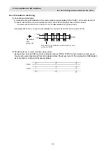
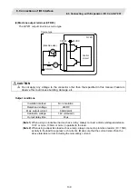
9.2.2 FCU7-DA201-11 / FCU7-DA211-11 (When using PD25/PD27 power supply unit)
(1) Connections of PD25/PD27 power supply
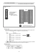
Y
Display unit
(Rear view)
FG
R
S
T
NFB
MC
PD25/PD27
power supply unit
F110 cable
ACIN
ON/OFF SW
ON/OFF
FAN ALARM
DCOUT
POWER
DCIN
CF01
DCIN
ON
OFF
ON/OFF switch
F170 cable
(Note 1)
CF01 (ACFAIL input: power supply shutoff notification signal) will not be used. Leave it
unconnected.
(Note 2)
PD25/PD27 cannot be turned ON immediately after it is turned OFF. Wait at least 2 seconds, and
then turn the power ON.
<Related items>
Cable drawing: "Appendix 2 (F110 cable, F170 cable)"
Connector pin assignment: "Appendix 3 (DCIN connector, CF01 connector)"
(2) Specifications of PD25/PD27 power supply
Refer to the section "6.2.2 When Using PD25/PD27 Power Supply Unit" for details on PD25/PD27.
CAUTION
Do not apply voltages to the connectors other than voltages indicated in this manual. Failure to observe this could
cause the devices to rupture or damage, etc.
Incorrect connections could cause the devices to damage. Connect the cable to the designated connector.
Do not connect or disconnect the connection cables between each unit while the power is ON.