[
IX
Troubleshooting ]
- 125 -
HWE10060
GB
LEV
-4- LEV
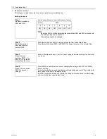
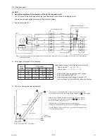
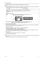
1. General descriptions of the operation of the LEV in the main circuit
LEV1 is driven by the pulse signal from the circuit board and is controlled by a stepping motor.
The valve opening changes according to the number of pulses
1) Control board and LEV
2) Pulse signal output and valve operation
3) LEV valve closing and opening operatio
Note. The connector numbers on the intermediate connector and the connector on the control board differ. Check the color of the lead wire
to judge the number.
Outdoor control board
Drive circuit
LEV
M
5
5
2
2
1
1
3
3
4
4
6
6
DC12V
Red
Intermediate connector
Brown
Blue
Orange
Yellow
White
Red Orange
White
Brown
Blue
Yellow
6
5
4
4
3
2
1
3
2
1
4
3
2
1
Connector CNLVE
Output state
Output
(phase)
number
1
2
3
4
1
ON OFF OFF ON
2
ON ON OFF OFF
3
OFF ON ON OFF
4
OFF OFF ON ON
Output pulses change in the following orders when the
Valve is closed; 1 2 3 4 1
Valve is open; 4 3 2 1 4
*1. When the LEV opening angle does not change,
all the output phases will be off.
*2. When the output is open phase or remains ON,
the motor cannot run smoothly, and rattles and vibrates.
*Upon power on, a 2260 pulse signal is sent to the LEV to determine the
valve position and bring the valve to the position indicated by " A " in the diagram
When the valve operates smoothly, no sound from LEV or no vibration
occurs, however, when the pulses change from E to A in the chart or
the valve is locked, a big sound occurs.
*Whether a sound is generated or not can be determined by
holding a screwdriver against it, then placing your ear against the handle.
*If liquid refrigerant is present in the LEV, it may make the operating sound
of the LEV difficult to detect.
2000 pulses
V
alve opening (refrigerant flow rate)
Valve closed
Valve open
E
B
Extra closure range (80 - 120 pulses)
Pulses
Fully open
A
C
D
Содержание CAHV-P500YA-HPB
Страница 1: ...Service Handbook Service Handbook CAHV P500YA HPB Model 2011 HOT WATER HEAT PUMP ...
Страница 7: ...CONTENTS HWE10060 GB ...
Страница 9: ... 2 HWE10060 GB ...
Страница 19: ... 12 HWE10060 GB ...
Страница 37: ... 30 HWE10060 GB ...
Страница 46: ... 39 HWE10060 GB IV Remote Controller 1 Using the Remote Controller 41 2 Function Settings 46 ...
Страница 47: ... 40 HWE10060 GB ...
Страница 55: ... IV Remote Controller 48 HWE10060 GB ...
Страница 56: ... 49 HWE10060 GB V Electrical Wiring Diagram 1 Electrical Wiring Diagram 51 ...
Страница 57: ... 50 HWE10060 GB ...
Страница 61: ... V Electrical Wiring Diagram 54 HWE10060 GB ...
Страница 62: ... 55 HWE10060 GB VI Refrigerant Circuit 1 Refrigerant Circuit Diagram 57 2 Principal Parts and Functions 58 ...
Страница 63: ... 56 HWE10060 GB ...
Страница 67: ... VI Refrigerant Circuit 60 HWE10060 GB ...
Страница 69: ... 62 HWE10060 GB ...
Страница 101: ... VII Control 94 HWE10060 GB ...
Страница 103: ... 96 HWE10060 GB ...
Страница 109: ... VIII Test Run Mode 102 HWE10060 GB ...
Страница 111: ... 104 HWE10060 GB ...
Страница 155: ... IX Troubleshooting 148 HWE10060 GB ...
Страница 156: ... 149 HWE10060 GB X Attachments 1 R407C saturation temperature table 151 ...
Страница 157: ... 150 HWE10060 GB ...
Страница 159: ... X Attachments 152 HWE10060 GB ...

