[
VII
Control ]
- 77 -
HWE10060
GB
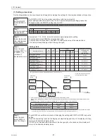
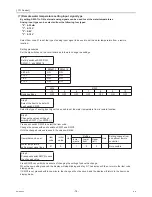
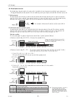
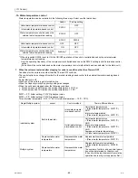
(9) Setting the booster heater operation conditions
A temperature at which the booster heater will go into operation (TWL) can be selected.
Select item code 1052 to set the threshold temperature (TWL) for booster heater operation.
Booster heater operation conditions
• Individual system
The operation command signal is ON and at least one of the following four conditions is met.
The booster heater signal of the MAIN circuit comes on.
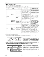
• Multiple system
The operation command signal is ON and at least one of the following three conditions is met.
The booster heater signal of the MAIN circuit comes on.
Booster heater operation-stop conditions
The operation command signal is OFF or all of the following three conditions are met.
(*)Unit's inlet water temperature: Average value between the water temperature settings of the MAIN and SUB
circuits
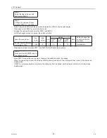
Setting procedures
Set the dip switches on the circuit board as follows to change the settings.
1 Both the MAIN and SUB circuits are sending the abnormal signal stop signals, or the
local switch of the SUB circuit is turned off.
2 The unit has been forced to stop due to abnormal outside temperature.
3 Water-temperature control option is set to OFF, and the water inlet temperature (*)
drops below TWL.
4 Water-temperature control option is set to ON, and the external water temperature
sensor reading drops below TWL.
1 Both circuits of all units are sending the abnormal stop signal, or the local switches of
all circuits on all units except the MAIN circuit to which the external temperature
sensor is connected are turned off.
2 The MAIN circuit of the main unit has been forced to stop due to abnormal outside
temperature.
3 External water temperature sensor readings (TH14 and TH15) drop below TWL.
1 None of the circuit is sending the abnormal stop signal, or the local switch of any of
the circuit is not turned off.
2 The MAIN circuit of the main unit has not been forced to stop due to abnormal outside
temperature.
3 One of the following conditions is met:
a. Water-temperature control option is set to OFF, and the water inlet temperature (*)
exceeds TWL+2°C.
b. Water-temperature control option is set to ON, and the external temperature sensor
readings (TH14 and TH15) exceed TWL+2°C.
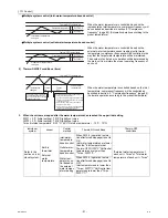
Step 1
Set dip switches
SW2 and SW3.
3
W
S
2
W
S
-10
5
6
7
8
9
10
Switch settings
OFF
OFF
OFF
OFF
OFF
ON
OFF
Содержание CAHV-P500YA-HPB
Страница 1: ...Service Handbook Service Handbook CAHV P500YA HPB Model 2011 HOT WATER HEAT PUMP ...
Страница 7: ...CONTENTS HWE10060 GB ...
Страница 9: ... 2 HWE10060 GB ...
Страница 19: ... 12 HWE10060 GB ...
Страница 37: ... 30 HWE10060 GB ...
Страница 46: ... 39 HWE10060 GB IV Remote Controller 1 Using the Remote Controller 41 2 Function Settings 46 ...
Страница 47: ... 40 HWE10060 GB ...
Страница 55: ... IV Remote Controller 48 HWE10060 GB ...
Страница 56: ... 49 HWE10060 GB V Electrical Wiring Diagram 1 Electrical Wiring Diagram 51 ...
Страница 57: ... 50 HWE10060 GB ...
Страница 61: ... V Electrical Wiring Diagram 54 HWE10060 GB ...
Страница 62: ... 55 HWE10060 GB VI Refrigerant Circuit 1 Refrigerant Circuit Diagram 57 2 Principal Parts and Functions 58 ...
Страница 63: ... 56 HWE10060 GB ...
Страница 67: ... VI Refrigerant Circuit 60 HWE10060 GB ...
Страница 69: ... 62 HWE10060 GB ...
Страница 101: ... VII Control 94 HWE10060 GB ...
Страница 103: ... 96 HWE10060 GB ...
Страница 109: ... VIII Test Run Mode 102 HWE10060 GB ...
Страница 111: ... 104 HWE10060 GB ...
Страница 155: ... IX Troubleshooting 148 HWE10060 GB ...
Страница 156: ... 149 HWE10060 GB X Attachments 1 R407C saturation temperature table 151 ...
Страница 157: ... 150 HWE10060 GB ...
Страница 159: ... X Attachments 152 HWE10060 GB ...

