[
VIII
Test Run Mode ]
- 98 -
HWE10060
GB
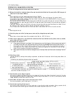
(10) Check for proper circulating water flow rate.
Measure the circulating water flow rate, if possible. If it is not, check that the temperature difference between the outlet and
inlet temperatures is between 3 and 5 ºC. A temperature difference of 6ºC or more indicates not enough water flow. Check
for air pockets in the pipe, and make sure that the pump has the appropriate capacity for the circuit.
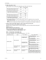
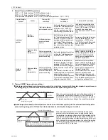
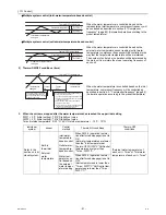
(11) Check that the unit is operating properly according to the temperature adjustment function.
When a pull-down operation is completed, check that the hot water temperature adjustment function will come on and that the
unit will automatically go on and off. Make sure the ON/OFF cycle (beginning of an operation until the next) is at least 10 min-
utes. (The unit features an anti-short-cycling protection.)
Notes on temperature adjustment function
The water temperature can be controlled based on the inlet or the outlet temperature sensor reading. Select one to use. Refer
to "VII [1]1.Factory Switch Settings (Dip switch settings table) and "(1)Setting procedures"(page 67) for how to select the water
temperature control method and how to set the water temperature.
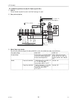
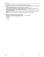
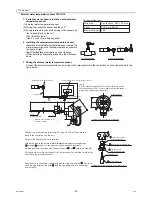
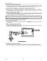
(12) Connect the pump-interlock wire to the appropriate contacts.
1) Connecting the pump-interlock wire
Connect the pump-interlock wire to the pump-interlock circuit (Terminal block and ). The unit will not operate unless this
circuit is complete.
2) Notes on connecting the pump-interlock wire
Connect an NO relay (solenoid switch) for the pump.
This circuit is a low-voltage circuit. Keep the pump-interlock wire at least 5 cm away from any wire that carries a voltage of
100 V or above to avoid damage to the circuit board.
(13) Checking the rotation direction of the pump
Check that the circulating water pump is rotating in the correct direction. If the pump is rotating in the wrong direction,
disconnect the pump wiring from the solenoid switch, and reconnect them so that the pump will rotate in the correct direction.
Do not disconnect the power wire to the compressor in an attempt to keep the compressor from going into operation
during test run. (If it is done, the control board will not sense that the compressor is stopped, and the water temperature
will not be controlled properly and the unit may come to an abnormal stop.)
11
12
MP
51P
52P
52P
51P
71
3
1
70
PL pump fault
Recommended pump circuit
F
M
3
㨪
Control board on the unit
Control box on the unit
11
12
52P
Содержание CAHV-P500YA-HPB
Страница 1: ...Service Handbook Service Handbook CAHV P500YA HPB Model 2011 HOT WATER HEAT PUMP ...
Страница 7: ...CONTENTS HWE10060 GB ...
Страница 9: ... 2 HWE10060 GB ...
Страница 19: ... 12 HWE10060 GB ...
Страница 37: ... 30 HWE10060 GB ...
Страница 46: ... 39 HWE10060 GB IV Remote Controller 1 Using the Remote Controller 41 2 Function Settings 46 ...
Страница 47: ... 40 HWE10060 GB ...
Страница 55: ... IV Remote Controller 48 HWE10060 GB ...
Страница 56: ... 49 HWE10060 GB V Electrical Wiring Diagram 1 Electrical Wiring Diagram 51 ...
Страница 57: ... 50 HWE10060 GB ...
Страница 61: ... V Electrical Wiring Diagram 54 HWE10060 GB ...
Страница 62: ... 55 HWE10060 GB VI Refrigerant Circuit 1 Refrigerant Circuit Diagram 57 2 Principal Parts and Functions 58 ...
Страница 63: ... 56 HWE10060 GB ...
Страница 67: ... VI Refrigerant Circuit 60 HWE10060 GB ...
Страница 69: ... 62 HWE10060 GB ...
Страница 101: ... VII Control 94 HWE10060 GB ...
Страница 103: ... 96 HWE10060 GB ...
Страница 109: ... VIII Test Run Mode 102 HWE10060 GB ...
Страница 111: ... 104 HWE10060 GB ...
Страница 155: ... IX Troubleshooting 148 HWE10060 GB ...
Страница 156: ... 149 HWE10060 GB X Attachments 1 R407C saturation temperature table 151 ...
Страница 157: ... 150 HWE10060 GB ...
Страница 159: ... X Attachments 152 HWE10060 GB ...


