E −
29
ENGLISH
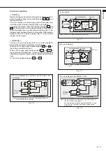
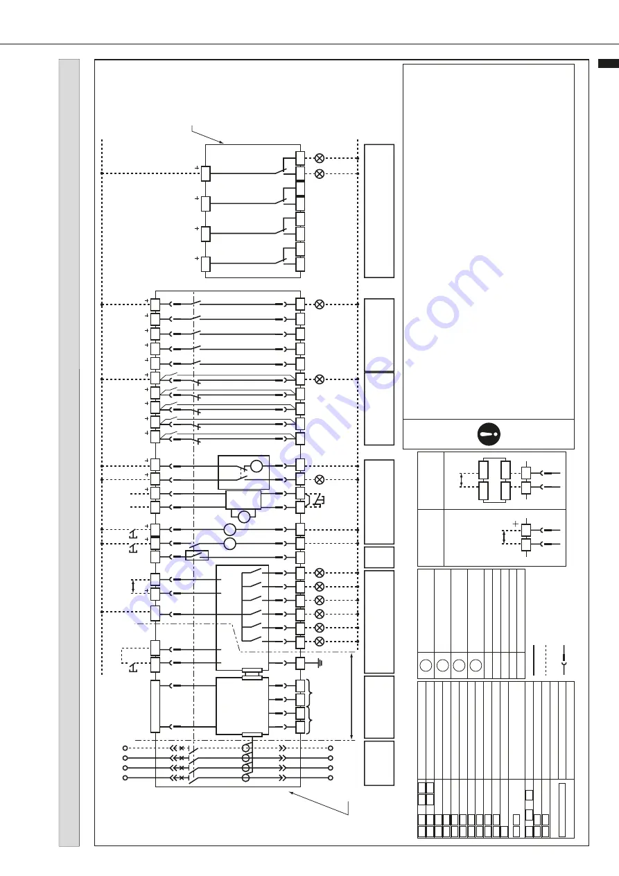
Wiring diagram
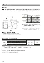
Fig. 29-1
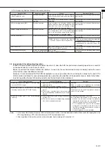
¡
On the dr
aw
out type
, the cab
les should ha
ve the length which allo
w the control circuit ter
minal b
loc
k to be mo
ved to the left or r
ight b
y
5 mm.
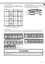
¡
When a coil load is connected in the same control circuit as the ETR, surge absorbers are required to absorb the surge v
oltage
(electromotiv
e f
orce).
¡
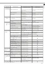
OCR alar
m (AL)
The contact output of the OCR alar
m (Standard type AL) is the one-pulse output (30-50 ms).
For this reason, this output needs self-holding circuit.
¡
In case of type P3 or P4, the alar
m contact output rela
y is high sensitiv
e rela
y.
Theref
ore ma
y occur a chatter
ing noise (appro
ximately
1ms) b
y ON/OFF oper
ation of the break
er
. Please adopt a time constant filter of se
ver
al ms
, or doub
le-reading (sampling), or the lik
e.
¡
Closing coil (CC)
Do not use AXb contact f
or a cut-off s
witch, because pumping pre
vention is not perf
or
med.
¡
Under v
oltage tr
ip de
vice (UVT)
As the pushb
utton s
witch f
or tr
ipping, use a s
witch ha
ving a contact capacity of 150
V DC
, 0.5 A or more
.
A shor
t-circuiting bar has been fitted to the tr
ip ter
minals
. Bef
ore using the tr
ip ter
minals
, remo
ve the bar
.
Disconnect the v
oltage input wires dur
ing dielectr
ic testing of main circuit.
¡
From some ter
minals are polar
ized, the wir
ing should be done correctly as to the polar
ity sho
wn in the wir
ing diag
ram when the
control v
oltage is DC
. A
uxiliar
y s
witch (AX) Standard type has no polar
ity
.
¡
Reset Circuit
As the pushb
utton s
witch f
or resetting the tr
ip indicator
, use a s
witch ha
ving a contact capacity of 15V DC
, 10mA or more
.
Electronic tr
ip
rela
y (ETR)
ETR
control v
oltage
Ref
er to
under tab
le
Cell s
witch
RESET
Charged
OFF
Reset circuit
P
ow
er circuit
Shor
t
bar
FG
NCT
(Note)
ZCT
Dielectr
ic
test f
orbidden
Main circuit
Break
er
Ter
minal descr
iption
Accessor
y Symbols
Electronic tr
ip
rela
y
Control po
w
er circuit /
alar
m contact
Electronic oper
ation
circuit
Cell s
witch
OCR
alar
m
A
uxiliar
y s
witch
(“b”
contact)
A
uxiliar
y s
witch
(“a”
contact)
Pushb
utton
for tr
ipping
(2 m or less)
A
uxiliar
y s
witch
“a”
contact
A
uxiliar
y s
witch
“b”
contact
F
or motor charging po
w
er
Charged signal
V
oltage input ter
minal of UVT
Tr
ip ter
minal of UVT
F
or control of closing coil
F
or control of shunt tr
ipping
OCR alar
m
P
ow
er supply f
or ETR
FG:
F
rame g
round
Alar
m reset (T
rip cause LED
,
alar
m contact)
Tr
ip cause
, alar
m contact output
ZCT connecting ter
minal
NCT connecting ter
minal
Displa
y unit connecting ter
minal
Interf
ace unit connecting ter
minal
VT unit connecting ter
minal
Shunt tr
ipping de
vice
Closing coil
Motor f
or charging
UVT coil
A
uxiliar
y s
witch
OCR alar
m s
witch
Charging completion s
witch
Shor
t-circuit B-contact
Cell s
witch
Inter
nal wir
ing
Exter
nal wir
ing
(User’
s wir
ing)
Control circuit connector (dr
aw
out type)
Extension ter
minals
A1
C1
97
P2
P1
N1
N2
Z1
Z2
P4
98
C2
A2
513
DT2
DT1
414
U2
D2
D1
413
U1
52
14
24
34
44
54
12
22
32
42
574
564
554
544
534
524
RS2
RS1
13
23
33
43
53
N
(2 m or less)
L3
L2
L1
CL1
CL2
CL3
CL4
CL
344
342
334
332
324
322
314
312
311
321
331
341
ON
OFF
Common
51
SBC
CLS
AX
AX
SBC
AX
SBC
AL
AX
AX
AX
AX
11
21
31
41
UVT
CC
UVT
controller
Cut-off
switch
Extension ter
minal
ON
13
14
11
12
U1
U2
413
414
D1
D2
DT1
DT2
A1
A2
C1
C2
97
98
P1
P2
P4
RS1
RS2
524
to
513
,
574
to
53
54
to
51
52
Z1
Z2
N1
N2
M
UVT
CC
SHT
AL
AX
SBC
AX
SBC
AX
SBC
AX
CLS
M
100-120
V A
C type
200-240
V A
C type
All DC type
380-460
V A
C type
(Note:) Please do not connect NCT f
or AE-SS
.
UVT controller wir
ing
V
oltage input
D1
D2
D1
D2
V
oltage input
Exter
nal unit
IN1
IN2
OUT3
OUT4
ERR
T AL
P AL
G1/E1/AP
STD/INST
LTD
SHT
* The following wiring diagram is for a fully equipped breaker.
Содержание AE-SW Series
Страница 78: ...ӄཐଆ D 49 ...
Страница 79: ...ӄཐଆ D 4 CHINESE ቲྲྀ ...


