E −
12
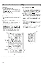
TEST position
Latch
Release
position
Cover
Push
Lock plate
Lock position
5
Push the lock plate in fully until it is latched to release
the lock.
(Note:)
(a) If the lock plate is not fully released, turn the
drawout handle to right and left a little.
(b) Be sure to push the lock plate in fully to release
position, otherwise the drawout position indicator
may not function collectoly.
Fig. 12-1
7
When the breaker is inserted to the test position, the
drawout position indicator shows TEST position, and the
lock plate automatically protrudes to lock the drawout
handle.
Fig. 12-3
7
Insert the breaker until the lock plate protrudes. If it does
not protruding, the breaker may not be connected com-
pletely.
6
After releasing the lock plate, turn the drawout handle
clockwise.
(Note:)
(a) Do not try to pull the unit out while inserting it as
doing so may not accurately display the posi-
tion. If the unit is pulled out in the middle of the
inserting process, pull it out to the circuit dis-
connecting position and then insert it again.
Fig. 12-2
6
8
Then, push the lock plate to turn the handle clockwise.
When the breaker is inserted to the connect position,
the lock plate automatically protrudes to indicate that
the breaker has been inserted completely. The drawout
position indicator shows CONNECT position.
(Note:)
(a) After insertion is completed, do not turn the
drawout handle further.
(b) The drawout position indicator shows the position
(CONNECT or TEST) of the breaker at the time
when the lock plate protrudes. When the lock
plate is in the released state, the indicator shows
the reference position.
(c) It is impossible to close the breaker when insert-
ing the drawout handle.
8
Check 1
The lock plate is jutted
out.
Automatic
Check 2
CONNECT (Connection)
position
Fig. 12-4
CAUTION
5
9
Fig. 12-5
9
For the AE4000 ~ 6300-SW series (See Fig. 12-5), shall
be sure to tighten the screws on both sides to secure
the breaker.
Содержание AE-SW Series
Страница 78: ...ӄཐଆ D 49 ...
Страница 79: ...ӄཐଆ D 4 CHINESE ቲྲྀ ...


