background image

6

– English

English

4

A

A

B

B

3

264 mm

78 mm

288 mm

176 mm

STEP 3

PRELIMINARY INSTALLATION WORK

Before proceeding with installation, check the condition of the product
components, suitability of the selected model and conditions of the
intended installation environment.

IMPORTANT

– The gearmotor cannot be used to power a manual

gate that does not have a fully efficient and safe mechanical struc-
ture. Neither can it solve defects caused by poor installation or insuf-
ficient maintenance of the door itself.

3.1

– CHECKING SUITABILITY OF THE ENVIRONMENT

AND THE GATE TO BE AUTOMATED

• Ensure that the mechanical structure of the gate complies with current
national standards and that it is suitable for automation. 

(If present, refer

to the information specified on the gate dataplate)

.

• Move the gate leaf manually to 

open

and 

close

, checking that move-

ment has the same degree of friction throughout all points of travel 

(no

increase in friction must occur)

.

• Manually move the leafs to any position and leave stationary, ensuring
that they do not move from this position.

• Ensure that the space around the gearmotor enables safe and easy
manual gate release. (see chapter “

Manually releasing or locking the

gearmotor

” in the “Operation manual”).

• Ensure that the selected surfaces for installation of the various devices
are solid and guarantee a stable fixture.

• Ensure that all devices to be installed are in a sheltered location and pro-
tected against the risk of accidental impact.

• Ensure that the selected surfaces for fixing the photocells are flat and
enable correct alignment between photocells.

3.2

– CHECKING PRODUCT APPLICATION LIMITS

To ascertain suitability of the product with respect to the specific features
of the gate and area to be automated, the following checks should be per-
formed as well as a check for compliance of the technical data in this
paragraph and the chapter “

Product technical specifications

”.

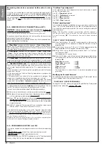
IMPORTANT – For the checks below, refer also to 

fig. 3

and 

4

:

– 

Fig. 3

: indicates the overall dimensions of the gearmotor.

– 

Fig. 4

: indicates values 

A

and 

B

, i.e. the minimum and maximum meas-

urements to observe when locating the position for the foundation plate.

Note 

– 

These measurements also serve as a reference to calculate the

space occupied by the foundation pit for routing the electrical cable ducting.

• Ensure that the dimensions and weight of the gate are within the follow-
ing limits of use.

maximum length 5 m

(

*

); 

maximum weight 300 kg

.

(

*

Note

– The e rack supplied with this product is suitable for automation

of a gate with leafs of a maximum length of 4 m. If necessary, this may be
extended to a maximum length of 5 m using rack mod. MR1 (2 sections of
50 cm).

• Ensure that the dimensions of the selected area for mounting the gear-
motor is compatible with the overall dimensions.

• On the gate leaf, ensure that the surface for mounting the rack is suit-
able and solid.

CAUTION! 

– If the results of these checks do not conform to

specifications, this model cannot be used for automation of
your gate.

30 mm

30 mm

40 mm

40 mm

Left-hand positioning of the gearmotor

Right-hand positioning of the gearmotor

Содержание Moovo LN4 Series

Страница 1: ......

Страница 2: ...unit 12 6 2 Installing and connecting flashing light mod MF 12 6 3 Installing and connecting photocells mod MP 14 Selecting the photocell pair operating mode 15 6 4 Installing and connecting keypad m...

Страница 3: ...If this is the first time you are setting up an automation for sliding gates we recommend that you read this entire manual with care This is prefer able before any work without any hurry to start prac...

Страница 4: ...trol unit can memorise up to 150 keys of MT4 transmitters up to 4 MK control keypads or alternatively up to 4 pairs of MP photocells set for the opening command only Connections of the various devices...

Страница 5: ...f accidental impact Ensure that the selected surfaces for fixing the photocells are flat and enable correct alignment between photocells 3 2 CHECKING PRODUCT APPLICATION LIMITS To ascertain suitabilit...

Страница 6: ...nals on the control unit mixed this configuration is a combination of the two configurations described above To select the most suitable connection configuration for the connection of all system devic...

Страница 7: ...edded in concrete and other preparation work for the installation can be com pleted to finalise the site ready for subsequent installation operations In particular for digging the pit for anchoring th...

Страница 8: ...fectly level use a spirit level 04 When the concrete is solid after a few days loosen and remove the upper nuts of the plate which are no longer required 05 Remove the gearmotor cover using a screwdri...

Страница 9: ...t so move the bracket to this position and if necessary use a hacksaw to cut off the excess section of the rack leaving a free section of approx 5 cm IMPORTANT the rack must not protrude from the gate...

Страница 10: ...NECTIONS OF SYSTEM DEVICES Install and connect the system devices with reference to the STEPS below and the example in fig 17 CAUTION Incorrect connections can cause faults or hazards therefore ensure...

Страница 11: ...icates execution of each manoeuvre It is also con nected to the diagnostics system of the control unit and in the event of malfunctions signals the type of problem by means of a pre set sequence of fl...

Страница 12: ...the cap of the flashing unit in its seat until the tabs click in place 21 20 22 08 Fig 23 Refit the transparent cover in its seat and turn clockwise taking care that the serrated section engages with...

Страница 13: ...p by pushing down one side as shown in the figure 02 Fig 26 Using a screwdriver open and detach the base of the photocell 03 Fig 27 a Drill a hole on the pre cut section on the base for routing the co...

Страница 14: ...oceed as follows 01 Open the cover of the photocell 02 In fig 31 locate the position in which the specific photocells are installed 03 In Table 2 select the required configuration and insert electric...

Страница 15: ...ypad cover by pushing down one side as shown in the figure 02 Fig 33 Using a screwdriver open and detach the base of the keypad 03 Fig 34 a Drill a hole on the pre cut section on the base for routing...

Страница 16: ...id the risk of leaks of harmful sub stances Battery disposal CAUTION Even if discharged the batteries can contain pollutant sub stances and therefore must NEVER be disposed of in common waste col lect...

Страница 17: ...nnections refer also to the paragraph What to do if 41 L2 green led L1 red led Key P1 STEP 7 WARNINGS The PVC power supply cable supplied serves exclusively for automation operation and programming te...

Страница 18: ...ing light 1 flash and the keypad 1 beep if fitted on the system 05 on the keypads Activate the keypads if fitted on the system by pressing any key on each one as required Successful learning is confir...

Страница 19: ...ey for example Command 2 03 Press P1 on the Control unit the same number of times as the selected command number in the example 2 i e twice and check that the green led emits the same number of quick...

Страница 20: ...press key T3 Leaf deceleration points press key T4 04 Lastly refer to Table 3 select the required value in correspondence with the selected function and on the transmitter press the key asso ciated w...

Страница 21: ...s first then the red led illuminates after 5 seconds and then both to indicate that the Control unit has entered memory deletion mode Then release the key 02 With reference to Table 4 select the data...

Страница 22: ...version of movement The automation does not respond to commands After a series of manoeuvres sent consecutively the automation is blocked The automation does not respond to commands The automation doe...

Страница 23: ...rictly observed In the case of this product the cable supplied may need to be replaced with a protected electric line suited to the installation In this case use a power cable with the dimensions 3 x...

Страница 24: ...ll devices used and the declaration of conformity compiled by the installer see section TECHNICAL DOCUMENTATION 2 Affix a dataplate on the door specifying at least the following data type of automatio...

Страница 25: ......

Страница 26: ...ered and sends the output signals Absorbed power 120mW in funzionamento 45mW in stand by Ambient operating temperature 20 50 C Use in acid saline or potentially No explosive atmospheres Assembly Verti...

Страница 27: ......

Отзывы: