


English –
25
AUTOMATION TESTING
1
Ensure that all specifications in STEP 1 regarding safety have been
strictly observed.
2
Using the transmitter, perform gate opening and closing tests and
ensure that the leaf movement corresponds to specifications.
Test several times to assess smooth operation of the gate and check
for any defects in assembly or adjustment and any possible points of
friction.
3
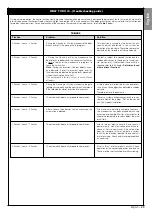
Check operation of all system safety devices one at a time (photocells,
sensitive edges, etc.). Photocells: Activate a single pair of photocells
during a manoeuvre (see
Table 2
to identify which manoeuvre to per-
form) and check that the control unit stops the manoeuvre and acti-
vates a total inversion of the movement (the flashing light emits 2 flash-
es, twice). Sensitive edges: Activate the device during an
Opening
or
Closing
manoeuvre and check that the control unit stops the manoeu-
vre and activates a brief inversion of the movement (the flashing light
emits 2 flashes, twice).
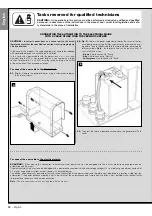
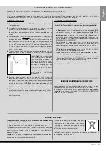
4
To check the photocells, and to ensure there is no interference with oth-
er devices, pass a cylinder (diameter 5 cm, length 30 cm) through the
optic axis joining the pair of pho-
tocells (
fig. 45
): pass the cylinder
first close to the TX photocell,
then close to the RX and lastly at
the centre between the two .
Ensure that in all cases the device
engages, changing from the
active status to alarm status and
vice versa, and that the envis-
aged action is generated in the
control unit (for example move-
ment inversion in the
Closing
manoeuvre).
5
Measure the force as specified in the standard EN 12445. If the motor
force control is used by the control unit as an auxiliary function for
reduction of impact force, adjust the functions “Leaf movement speed”
and “Leaf deceleration points” (Chapter 10) to identify the setting that
obtains the best results.
CAUTION!
– If the gate weighs more than 200
kg, to ensure compliance with the parameters in the standard EN
12453, a flexible edge must be fitted at the end of the gate.
6
To check operation of the buffer battery, on completion of charging, test
as follows: disconnect the power supply and after a few seconds check
that the leds and flashing light emits a series of 5 flashes. If this does
not occur, check that the battery connector is correctly inserted and
invert if necessary.
AUTOMATION COMMISSIONING
Commissioning can only be performed after positive results of all test
phases. Partial or “makeshift” commissioning is strictly prohibited.
1
Prepare the automation technical documentation, which must contain
the following documents: Overall layout drawing (see example in
fig. 5
),
and electrical connection layout diagram (see example
fig. 17
) risk
assessment and relative solutions adopted (see the website
www.moovo.com
for a guide to risk assessment for different types of
gates), manufacturer’s declaration of conformity for all devices used
and the declaration of conformity compiled by the installer (see section
TECHNICAL DOCUMENTATION).
2
Affix a dataplate on the door, specifying at least the following data: type
of automation, name and address of manufacturer (responsible for
commissioning), serial number, year of construction and CE mark.
3
Prepare and provide the owner with the declaration of conformity; the
“
CE Declaration of conformity
”
in the section TECHNICAL DOCU-
MENTATION must be compiled for this purpose.
4
Prepare and provide the owner with the form
“
Operation manual
”
in
the section TECHNICAL DOCUMENTATION .
5
Prepare and provide the owner with the form
“
Maintenance schedule
”
in the section TECHNICAL DOCUMENTATION, containing all mainte-
nance instructions for all devices in the automation .
6
Before commissioning the automation, ensure that the owner is ade-
quately informed of all associated risks and hazards.
AUTOMATION TESTING AND COMMISSIONING
These are the most important phases of automation set-up to ensure maximum system safety.
The testing procedure described can also be performed as a periodic check of automation devices.
Testing and commissioning of the automation must be performed by skilled and qualified personnel, who are responsible for the tests required to veri-
fy the solutions adopted according to the risks present, and for ensuring observance of all legal provisions, standards and regulations: and in particular
all requirements of the standard EN 12445, which establishes the test methods for checking automations for gates.
PRODUCT DISPOSAL
45
PERIODIC MAINTENANCE OPERATIONS
This product does not generally require any special maintenance; never-
theless, regular check-ups are advisable to ensure the system is in good
working order and that the safety devices installed work properly.
To carry out this maintenance correctly, please refer to the
“
Maintenance
Schedule
”
, which you will find in the “TECHNICAL DOCUMENTATION”
section at the end of the manual.
This product is an integral part of the automation and therefore must
be disposed together with the latter.
As in installation, also at the end of product lifetime, the disassembly and
scrapping operations must be performed by qualified personnel.
This product comprises various types of materials: some may be recycled
others must be disposed of. Seek information on the recycling and dis-
posal systems envisaged by the local regulations in your area for this
product category.
Caution!
– some parts of the product may contain pollutant or hazardous
substances which, if disposed of into the environment, may cause serious
damage to the environment or physical health.
As indicated by the symbol alongside, disposal of
this product in domestic waste is strictly prohibited
Separate the waste into categories for disposal,
according to the methods envisaged by current
legislation in your area, or return the product to the
retailer when purchasing a new version.
Caution!
- Local legislation may envisage serious fines in the event of
abusive disposal of this product.
English


