


English –
17
English
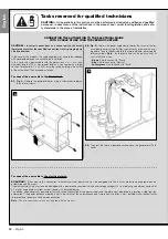
02.
Fig. 39:
Insert the battery connector in the male connector on the control
unit.
WARNINGS
To guarantee optimal lifetime of the buffer battery, the following warnings should be
observed:
•
When the buffer battery is completely discharged, around 24 hours are required to
completely recharge.
• The buffer battery is an emergency device: therefore in the event of a power failure,
only moderate use is advisable. Excessive and continuous use can lead to over-
heating of the elements, which over time may reduce the normal lifetime of the bat-
tery.
• In the event of a power failure, never leave the automation powered exclusively by
the buffer battery for periods longer than a day: The elements may overheat exces-
sively and impair lifetime of the battery.
Therefore, if absent from the installation site of the automation for prolonged peri-
ods, it is recommended to detach the buffer battery terminal connected to the
control unit.
• In the event of prolonged periods of disuse, the optional battery should be
removed and stored in a dry location to avoid the risk of leaks of harmful sub-
stances.
–––––––––––––––––––
Battery disposal
CAUTION!
– Even if discharged, the batteries can contain pollutant sub-
stances and therefore must NEVER be disposed of in common waste col-
lection points. Dispose of according to separate waste collection methods
as envisaged by current local standards.
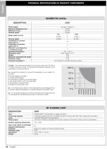
6.5
– INSTALLING BUFFER BATTERY mod. MB
The buffer batteries are self-charging with a voltage of 12V and power of
2100mAh. These are particularly useful in the event of a sudden power
failure. The gearmotor with control unit enables installation of 1 battery.
Depending on the type and weight of the gate, when charged, the battery
guarantees an autonomy of approx. 6 - 7 consecutive movement cycles
(1 cycle =
opening
-
closing
).
To install the buffer battery proceed as follows:
01.
Fig. 38:
Inside the gearmotor, insert the battery in the space alongside the
control unit.
CAUTION! – The point below (02 – electrical
connection of the buffer battery to the control
unit ) must only be performed after completing
all installation and programming phases, as the
battery is an emergency power source.
CAUTION! – For safety reasons, the buffer bat-
tery must only be installed after completing
installation and programming, and after check-
ing correct operation of the system.
38
39


