18. Interface specifications
MiR1000 Shelf Lift User Guide (en) 12/2020 - v.2.1 ©Copyright 2019-2020: Mobile Industrial Robots A/S.
230
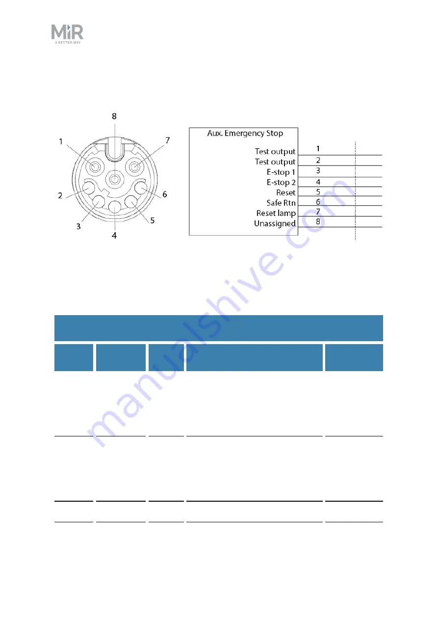
Auxiliary emergency stop
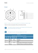
Figure 18.4. Pin numbers: female connector viewed from the front (left) and
wiring diagram (right).
The Auxiliary emergency stop interface is designed to support Emergency stop and other
safety functions—see
Emergency stop buttons on page 99
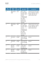
contains the description of the pins of the Auxiliary emergency stop interface.
Pin
number
Signal
name
Type
Description
Lift funct ion
1
Test output
Output
24 V output signal from the safety
PLC for the Emergency stop circuit.
Should connect to pin 3.
Connects to
pin 3 via the
Emergency
stop buttons
on the lift.
2
Test output
Output
24 V output signal from the safety
PLC for the Emergency stop circuit.
Should connect to pin 4.
Connects to
pin 4 via the
Emergency
stop buttons
on the lift.
3
E-stop 1
Input
Input signal to the safety PLC for
Connects to
Table 18.3.
Description of the pins in the Auxiliary emergency stop interface
Содержание 1000 Shelf Lift
Страница 1: ...User Guide en Date 12 2020 Revision v 2 1 ...


