background image

68

Service Manual Combics

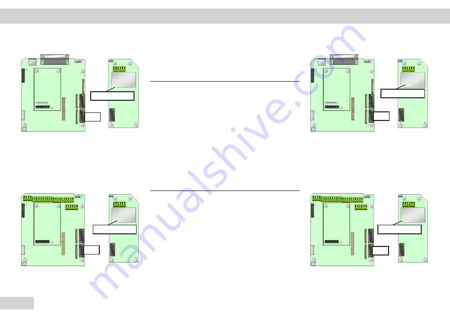
ADC Option (A10/A20) Pin Assignment

DSUB or screw terminals Combics 1 (on board, 
see left image) 1x10.000e

Connection Function

1   


EXC+

2   


SENSE+

3   


OUT+

4   


OUT-

5   


SENSE-

6   


EXC-

DSUB or screw terminals Combics 2/3 (see right 
image) 1x10.000e

Connection Function

1   


EXC+

2   


SENSE+

3   


OUT+

4   


OUT-

5   


SENSE-

6   


EXC-

A10, 1x10.000e

A10, 1x10.000e

A20, 1x10.000e

A20, 1x10.000e

Interface Description | PCBs

ST5

ST5

ST5

ST5

Содержание CAIS3

Страница 1: ...Austin Ft Worth NicolScales com 800 225 8181 Contact Us Nicol Scales Measurement is an ISO Accredited Calibration Company that has provided calibration repair and sales of all types of weighing and measurement products since 1931 ...

Страница 2: ...Intec Combics Series Models CAW IP69K IP44 Combics Complete Scales Models CAH CAS Combics High Resolution Complete Scales Models CAI IP69K IP44 Combics Complete Indicators Models CAAP Combics Weighing Platforms Service Manual ...

Страница 3: ...service mode 13 Service Mode 13 Activating the service mode for Combics CAIS1 CAISL1 CAIS2 CAISL2 13 14 Additional Menus in the Service Mode 15 Activating the Service mode for Combics CAIS3 CAISL3 16 Test Program for Combics Indicators 1 and 2 30 Test Preparation 32 Test Implementation 32 Test Results 35 Test Program for Combics Indicator 3 36 Test Preparation 36 Test Implementation 37 Test Result...

Страница 4: ...panded View Diagram 2 87 Refer to the spare parts list in ISSS 87 PCBs for Combics 87 Lower part 87 Expanded View Diagram 3 88 Lower part 88 Adjustment data 89 Test loads 89 Definition of Error 89 Description of testing procedures 89 Repeatability EN45501 3 6 1 8 2 A 4 10 89 Eccentricity EN45501 3 6 2 8 2 A 4 7 89 Weighing performance EN45501 8 2 A 4 4 1 89 Adjustment data 90 Adjustment data 90 De...

Страница 5: ...tions to provide a better overview Warning or Important Note 3 This safety relevant information must be followed If not followed it can lead to bodily harm or equipment damage After removing the seal marks warranty stickers and concluding the service work please seal the device with your company sticker Please note that in addition to the correct tools a stable and clean work space is required whi...

Страница 6: ... be performed when an insulating transformer or ground fault circuit interrupter is present Please see the operating instructions for additional safety and warning information Connecting and disconnecting cables may only be done after the equipment has been disconnected from the power Components can be destroyed 1 Always turn off the device via the ON OFF key e 2 Disconnect the power plug 3 The ap...

Страница 7: ...ered by Minebea Intec General Notes For device care and maintenance see User manual CAIS CAISL1 2 Publication no WCA6007 d10051 User manual CAIS CAISL3 Publication no WCA6008 d10051 Important h For more information please refer to User manual CAIS CAISL1 2 Publication no WCA6007 d10051 User manual CAIS CAISL3 Publication no WCA6008 d10051 Service manual for Combics Series Publication no WCI5003 d0...

Страница 8: ...g in non stainless steel or stainless steel with corresponding resolution options Indicator units are supplied in customized non stainless steel or stainless steel versions Indicator units also have three versions with a keypad in the front plate Model Description Protection class CAIS1 Indicator IP69K CAIS2 Indicator IP69K CAIS3 Indicator IP69K CAISL1 Indicator IP44 CAISL2 Indicator IP44 CAISL3 I...

Страница 9: ...2 Complete scale IP69K CAWIS3 Complete scale IP69K CAWISL1 Complete scale IP44K CAWISL2 Complete scale IP44K CAWISL3 Complete scale IP44K CAH1E 3E CAS Complete scale Indicator IP69K Weighing platform IP65 CAH1G 3G Complete scale Indicator IP69K Weighing platform IP65 Introductory Notes General ...

Страница 10: ...t be free of vibrations and air drafts For safety instructions refer to user manual User manual CAIS CAISL1 2 Publication no WCA6007 d10051 User manual CAIS CAISL3 Publication no WCA6008 d10051 User manual COMBICS KPL Scale Publication no WCA6009 d10081 User manual COMBICS KPL Scale Publication no WCA6010 d10081 Overview of Spare Parts or refer to the spare parts list in ISSS Positioning of Spare ...

Страница 11: ...Tools Quantity Description 1 Insulating transformer 1 AC DC multimeter 1 RS 232 485 interface converter 1 DMS simulator 1 Test connector for COM port test COM 1 1 Socket wrench set size 5 5 5 7 1 SartoCas H8S Introductory Notes General ...

Страница 12: ...ibration Print Data output CAIS12 CAISL2 Display On Off key General function keys Scale When connecting a second weighing platform the display switches between the platforms Zero Tare Switch function Adjustment Calibration Print Data output x10 Toggle unit between normal and 10 fold higher resolution B G Net Gross value Clear function Reference value Apply value Switch display Toggle between avail...

Страница 13: ...2 window is active for required adjustments characteristic value linearity CAIS3 CAISL3 Display graphic capable dot matrix display On Off key General function keys Scale When connecting a second weighing platform the display switches between the platforms Zero Tare Switch function Adjustment Calibration Print Data output x10 Toggle unit between normal and 10 fold higher resolution B G Net Gross va...

Страница 14: ...a preload or entering the service date See the respective service instructions for information on working with weighing platforms Information on calibration adjustment for new weighing platforms is contained in this manual under Calibration Adjustment Activating the service mode for Combics CAIS1 CAISL1 CAIS2 CAISL2 t Switch off Combics e key t Switch Combics on again e key and briefly press the k...

Страница 15: ...ssing the key several times t After entering the last number press the and keys in that order to activate the service mode y When the service mode is active an S appears in the top right of the display t If the entry routine of the service password is interrupted keep pressing the key until U CODE user code reappears on the display Important h You can only exit the service mode by turning the Comb...

Страница 16: ...he following options for configuration of weighing platforms WP 1 WP 1 and WP 2 WP 2 Important h The menu setting numbers are only visible when setting the active language CODES CODES 1 9 Calibration Adjustment functions 1 9 1 Ext calibration adjustment with default weights Service mode not required 1 9 3 Ext calibration adjustment with user defined weights Service mode not required 1 9 5 Internal...

Страница 17: ...tter S is displayed on the right in the Setup menu header The Setup menu has been expanded along with the User menu To view or change device parameters in Setup mode tSelect the Device parameters menu open the menu press the key yThe Device parameters sub menu opens t Select and open the desired menu item of the next lowest level Repeat this procedure until the desired menu item in the lowest menu...

Страница 18: ...thout changing settings by confirming with the M key or the oo soft key the Service mode will remain active Press the M key again to re open the Setup menu in the Service mode Operating Design Service Mode Combics3 WP 1 WP 2 COM 1 COM 2 I O control Bar code Config printout Operating parameters Clock Test I O ports Passwords Maintenance Terminal data SQmin Alibi Memory ...

Страница 19: ...s of the Calibration Adjustment menu also contain additional menu items If one of the COM 1 or COM 2 interfaces has been configured for connecting a 2nd weighing platform WP 2 then the additional menu items listed above for the Calibration Adjustment menu also apply to the weighing platform configured under WP 2 If necessary the ADC configuration menu is also accessible to WP 2 when connecting a s...

Страница 20: ...t Slide the switch to the left open position Enter the service password as described above 202122 confirm with the key and scroll back using the key y The device is now in Service mode The letter S is displayed on the right in the Setup menu header t Select the SETUP menu item Press the key t Select weighing platform and confirm Press the key t Select the INTERNAL menu item t Press the key setup W...

Страница 21: ...rrying out the required adjustments the adjustment function that the customer should carry out must be set Operating Design Service Mode Combics 1 2 ADC configuration S PARAM K ADU KON S y Standard configuration STANDRD Range selection RANGE Single range mode SINGLE D MAX Multi interval mode MULT INT D RANGE 1 RANGE 2 RANGE 3 MAX Multiple range mode MULT RNG D RANGE 1 RANGE 2 RANGE 3 MAX Unit sele...

Страница 22: ...g kilogram or ton KG T Save the ADC configuration SAVE Save NO Save Yes Once you have completed the configuration save the data in the menu item via Yes The A D converter can now be treated like any standard weighing platform in connection with the load sensor Important h Once ADC configuration has been completed an adjustment of the weighing platform calibration adjustment and linearization must ...

Страница 23: ...g a weighing platform WP 1 or WP2 to a Combics 1 or 2 Open the menu access switch t Remove the cap that covers the menu access switch on the back of the indicator t Slide the switch to the left open position y The device is now in STANDBY mode t Turn on the device with the e key y All segments light up in the display t While all segments are lit press the key Operating Design Service Mode Combics ...

Страница 24: ...ng platform was configured in the menu WP 1 appears in the display y If a second weighing platform is connected and configured in the menu you can switch to it by pressing the k key t Press the key t The weighing platform can no be configured For settings see ADC Configuration tClose the menu access switch Slide the menu access switch to the right closed position Operating Design Service Mode Comb...

Страница 25: ...ck left of the indicator t Slide the switch to the left open position Switch on the Combics 3 yThe scale is now in an application program i e Weighing application the example shows the Counting application t Enter the service password 202122 via the decimal keypad and confirm with the M key Operating Design Service Mode Combics 3 ADC configuration 202122 ...

Страница 26: ...next lowest level Repeat this procedure until the desired menu item in the lowest menu level can be opened View the menu item change if necessary confirm with the soft key and return to the highest level of the Setup menu via the soft key press several times if necessary tSelect a weighing platform e g WP 1 and confirm with the soft key Operating Design Service Mode Combics 3 ADC configuration WP ...

Страница 27: ...onfirm once more here with the soft key ADU 232 appears in the display Confirm once more using the soft key You can now begin ADC configuration Standard or Verifiable appears in the display The ADC can now be configured You will need to read the corresponding operating instructions for this Operating Design Service Mode Combics 3 ADC configuration ...

Страница 28: ...t key y ADU CON appears in the display tConfirm using the soft key y Standard Verifiable appears in the display The ADC can now be configured Important h You will need to read the corresponding operating instructions for this Operating Design Service Mode Combics 3 ADC configuration ...

Страница 29: ...u exit the Setup menu without changing settings by confirming with the M key or the oo soft key the Service mode will remain active Press the M key again to re open the Setup menu in the Service mode tClose the menu access switch Slide the menu access switch to the right closed position Operating Design Service Mode Combics 3 ADC configuration ...

Страница 30: ...or Psion service software without having to activate the BPI mode via the SBI BPI keypad Note This menu item can be accessed in the standard menu Setup Device parameters COM 1 Data communication XBPI RS 232 Note You can only assign addresses like those shown in the XBPI sub menu for the XBPI RS 485 constellation Operating Design XBPI Protocol Settings ...

Страница 31: ...tests can be canceled Version number information Test of the display Test of the keypad Test of internal components e g memory components Test of options and L9 battery Test of COM 1 interface Test of optional UNICOM interface if used The Combics 2 test program runs in the following sequence Information indicating how individual tests can be canceled Version number information Test of the display ...

Страница 32: ...ust then flash One or the other LEDs flashes depending on the interface configuration current or voltage output The service technician can make a visual inspection during the display test Each key can be checked for problem free functioning during the keypad test It must be possible to clearly feel and hear the click action of the key Important h Using the p key for Combics 1 or the c key for Comb...

Страница 33: ...options do not require a test adapter The test adapter must be supplied with a mains adapter 15V for option A5 Test Implementation tSwitch Combics to Standby mode tInsert the test adapter into the interfaces e g into COM 1 tPress and hold the k key tPress the e key to turn the device back on yYou will here a brief beep tone three times test has started tRelease the k key y The display shows inform...

Страница 34: ... on the display The keys that must be checked appear in sequence on the display t Carry out the keypad test All keys that need to be pressed appear on the display Keys should be pressed within 5 sec otherwise the program will see this as a key error y It must be possible to clearly feel and hear the click action of the key y Then the internal test of the memory components takes place The display s...

Страница 35: ...akes place for the optional UNICOM interfaces A different message appears on the display depending on the option OPT RS232 for option A1 OPT RS422 for option A2 OPT RS485 for option A3 OPT DIGITAL for option A5 OPT ANALOG for option A9 cancel test via the c key The LED flashes PROFIBUS for option B1 ETHERNET for option B9 y A test of the LED indicators for option A9 takes place 4 20mA 0 10V y The ...

Страница 36: ...the end of the test in the display e g COM 1 RS232 LOOPBACK If the program discovers multiple errors then these are displayed in succession Important h If several errors are displayed these should be noted and written down Pressing the t key displays the last error one more time Error list see Caution 3 If the display flashes then the key to cancel the test was pressed accidentally Disconnect the ...

Страница 37: ...ersion number information Test of the display Test of LEDs Test of the keypad Test of internal components e g memory components Test of options and L9 battery Test of COM 1 interface Test of COM 2 interface Test of optional UNICOM interface if used Test of internal clock RTC Important h Follow the instructions for Combics 1 and 2 Test Preparation Test adapters must be connected to the COM 1 and CO...

Страница 38: ...rt the test adapter into the interfaces e g into COM 1 tPress and hold the k key tPress the e key to turn the device back on yYou will here a brief beep tone three times test has started tRelease the k key yThe display shows the version number of the firmware t DISPLAY TEST appears on the display tThe display back lighting turns off and then on again yAll segments in the display are tested with a ...

Страница 39: ...ars on the display The keys that must be checked appear on the display t Carry out the keypad test All keys that need to be pressed appear on the display Keys should be pressed within 5 sec otherwise the program will see this as a key error y It must be possible to clearly feel and hear the click action of the key y Then an internal test takes places like with the Combics 2 Operating Design Test P...

Страница 40: ...these are all shown on the display contrary to Combics 2 Caution 3 If the display flashes then the key to cancel the test was pressed accidentally Disconnect the device from the power pull the plug Then reconnect the power plug and turn the device back on via the e key The device is ready for operation again tPress the e key to exit the program Operating Design Test Program Combics 3 ...

Страница 41: ...ored The following error messages are possible Operating Design Error Description Test Combics 1 2 3 Test Message Meaning Possible error sources None but Back light is always dark Display unit Cable defective Cable not inserted correctly into the digital PCB Digital PCB defective Back light is always light Display unit Cable defective Digital PCB defective Display not all segments are displayed Di...

Страница 42: ...ilable Alibi memory not detected Digital PCB defective Alibi memory defective Alibi memory not inserted correctly Battery Battery symbol does not appear If L9 is available No communication between digital PCB and battery controller Connection cable between digital PCB and battery controller not inserted or defective Battery controller defective Digital PCB defective SCL2 ADU NOT FOUND If A10 is av...

Страница 43: ...RS422 LOOPBACK TxD RxD loop back to UNICOM interrupted Test adapter missing PCB option defective or not inserted correctly into digital PCB Digital PCB defective OPT RS485 LOOPBACK TxD RxD loop back to UNICOM interrupted PCB option defective or not inserted correctly into digital PCB OPT DIGTAL INPUT Loop back between input and output interrupted Test adapter inserted incorrectly No 15V power supp...

Страница 44: ...on also depends on the type of interface If you are talking about CAIS devices IP69 without a cable then a standard cable must be connected to the associated adapter for the test at the corresponding screw terminals Test Adapter for Com 1 and Com 2 The connections can also be linked directly to the clamp connectors Test adapter for COM1 for interface options A1 and A2 The adapter wiring for the in...

Страница 45: ...screw terminals of the PCBs The connections are listed in the following table Test Adapter for Option A6 A62 RS 232 Adapter for interface options A6 and A62 connection for IS platforms Screw terminals are only available for this interface option Important h No adapter is required for option A7 A72 Operating Design Error Description Test Combics 1 2 3 ...

Страница 46: ...n LED indicators are used The wiring of the adapter is included in the following figure Important h The test adapter and test configuration for interface option A5 digital I O is more complicated because when there is a faulty interface PCB or if the error does not go away the main or digital PCB must be replaced Operating Design Error Description Test Combics 1 2 3 ...

Страница 47: ...lay Error messages are shown in the main display Error messages are shown permanently Information messages are shown for 2 seconds After this the program automatically returns to the weighing mode Operating Design Error Description Display Combics 1 2 3 ...

Страница 48: ...ck on again If Err 340 remains displayed Contact your local Service Center Err 343 Loss of data in the memory area for trans Contact your local Service Center action numbers in external alibi memory Inf 01 Data output not compatible with Set output format correctly output format inf 02 Calibration adjustment condition not met Calibrate only when zero is displayed e g the scale was not tared the sc...

Страница 49: ...r provides no or a much too low measured result A D converter control over maximum limits the A C converter provides a much too high measured result Cannot store the current weight value or entry e g control limits too low or too high Contact your local Service Center for information on changing settings Check whether in your configuration zero at power on 1 12 is set Zero the scale Place a heavie...

Страница 50: ... 74 Function is blocked None e g menu is locked inf 98 No weighing platform connected Connect a weighing platform inf 99 No weighing platform connected Connect a weighing platform NO WP No weighing platform connected Connect a weighing platform Operating Design Error Description Display Combics 1 2 3 ...

Страница 51: ... includes Front plate with keypad and digital display Combics indicators CAIS1 or CAISL1 come with either a D Sub 25 IP44 or cable glands IP69 The digital PCB see page 52 can also be integrated for option A6 A7 A10 Main PCB with H8S processor analog digital converter and DC DC converter Power supply PCB Unicom interfaces in several versions com1 interface in 2 versions Alibi memory optional Onboar...

Страница 52: ...ion A9 ALIBI MEMORY Alibi memory Option E5 Main PCB for IP69 version UNICOM RS 232 Option A1 RS 422 Option A2 RS 485 Option A3 Digital I O Option A5 4 20mA Option A9 Ethernet Option B9 Profibus Option B1 ALIBI MEMORY Alibi memory Option E5 Device Description Bu4 S1 LV3 Opt E5 ST3 ST4 ST7 BU6 ST6 ST1 COM1 S1 LV3 Opt E5 ST3 ST4 ST7 ST6 ST1 LV1 LV2 Opt A1 A3 A5 A9 Opt B1 B9 Opt A1 A3 A5 A9 B1 B9 ...

Страница 53: ... CAIS2 or CAISL2 come with either a D Sub 25 IP44 or cable glands IP69 Device Description Digital PCB with H8S processor and DC DC converter Power supply PCB Unicom interfaces in several versions com1 interface in 2 versions Alibi memory optional ADC option A8 2 3000e multi interval PS 2 interface possible in two versions ...

Страница 54: ... A9 B1 B9 Options for CAIS2 CAISL2 indicators Digital PCB for IP44 version with D SUB plug UNICOM RS 232 Option A1 RS 422 Option A2 RS 485 Option A3 Digital I O Option A5 4 20mA Option A9 ALIBI MEMORY Alibi memory Option E5 Main PCB for IP69 version UNICOM RS 232 Option A1 RS 422 Option A2 RS 485 Option A3 Digital I O Option A5 4 20mA Option A9 Ethernet Option B9 Profibus Option B1 ALIBI MEMORY Al...

Страница 55: ... either a D Sub 25 IP44 or cable glands IP69 Device Description Digital PCB with H8S processor analog digital converter and DC DC converter Power supply PCB or DC DC Unicom interfaces in several versions com1 interface in 2 versions Alibi memory optional E5 ADC 2 3000e multi interval Option A8 PS 2 interface ADC 10000e multi interval Option A10 20 ...

Страница 56: ...libi memory Option E5 Main PCB for IP69 version UNICOM RS 232 Option A1 RS 422 Option A2 RS 485 Option A3 Digital I O Option A5 4 20mA Option A9 Ethernet Option B9 Profibus Option B1 ALIBI MEMORY Alibi memory Option E5 Device Description BU4 S1 Opt E5 ST7 BU5 ST6 ST1 COM1 S1 Opt E5 ST3 ST4 ST7 ST6 ST1 LV1 LV2 BU2 BU3 ST4 ST5 BU6 COM1 LV4 LV3 ST2 ST4 ST5 BU2 BU3 BU1 PS 2 Opt A1 A3 A5 A9 Opt B1 B9 O...

Страница 57: ...5 7 65901 200 00 main board C2 3 X X X 7 65901 270 00 ADC 3 000e X 7 65901 260 00 interface board ADC RS485 X X 7 65901 220 00 ADC board 10 000e A8 ADC 2x 3 000e A6 RS232 A7 RS485 7 65954 210 00 main board C1 inkl ADC X 7 65954 200 00 main board C2 3 X X 7 65901 260 00 interface board ADC RS485 X X 7 65901 220 00 ADC Platine 10 000e A8 ADC 2x 3 000e A6 RS232 A7 RS485 7 65954 200 00 main board C2 3...

Страница 58: ...ion B9 Profibus Option B1 ALIBI MEMORY Alibi memory Option E5 Theft protection Option L7 INDUSTRIAL POWER SUPPLY 24V Option L8 Additional PCBs Connection for IS platforms RS 232 Option A6 A62 RS 485 Option A7 A72 ADC 2x3000e Option A8 1x10 000e Option A10 A20 Device Description B9 B1 A9 A5 A3 A1 L8 24V A6 A7 A62 A72 A10 A20 1x10 000e E5 E5 A8 2x3000e L7 Übersicht_Combics_01 tif ...

Страница 59: ...bics indicator Replacing the Seal Important h After carrying out any repair the seal between the front plate and the housing must be checked visually for damage and replaced if necessary After closing a special test procedure is used to check the degree of protection for devices that guarantee an IP degree of protection tReplace a defective seal yThe seal must be seated properly and should not be ...

Страница 60: ... front plate versions The Combics 1 indicator left includes Front plate with keypad and digital display The Combics 2 indicator left includes Front plate with keypad with number keys digital display and LEDs The Combics 3 indicator left includes Front plate with keypad and number keys digital display and LEDs Repairs Component replacement Front Plate ST 3 ST3 ST2 ST3 ST2 ST2 ...

Страница 61: ...he input of the main digital PCB plug B is 15V 0 8V direct voltage Remove the protective cover from the power supply PCB beforehand for measuring To do this insert a regular screwdriver into the four openings of the protective cover and carefully press the clips located at the bottom to the side Replacing the Power Supply PCB Remove the protective cover and the two cables blue brown of the power c...

Страница 62: ...atest care using a thin test probe danger of a short circuit The various supply voltages can be measured at the following measurement points M1 GND GND M2 M3 M4 Important h If no voltages are registered at the measurement points then replace the main PCB M 1 15 V 1 5 V input voltage for the DC DC converter M 2 3 3 V 0 2 V M 3 8 5 V 0 4 V M 4 8 5 V 0 4 V M 5 5 V 0 25 V h Repairs Component Replaceme...

Страница 63: ...t voltage for the DC DC converter M 2 3 3 V 0 2 V M 3 5 V 0 2 V M 4 8 V 0 5 V M 5 8 V 0 5 V M 6 17 V 2 V Important h If no voltages are registered at the measurement points then replace the digital PCB M5 M2 M6 M1 GND GND M3 M4 Repairs Component Replacement Measurement Points ...

Страница 64: ...PCB as already described The device power supply may be interrupted t Disconnect the device from the power and open it t Then replace the power supply cable t Insert the ground cable t Check the voltage Important h After replacing the power supply cable the cable gland should be tightened using a torque of 3 Nm Repairs Component Replacement Power Cord ...

Страница 65: ...he old weighing system to the controller of the new AD converter after replacement In many cases this negates the need to readjust the weighing system If the PCB has to be replaced the current software is already factory installed on the PCB Important h One of the Com 1 PCBs YDO01M 232 or YDO01M 232CLK is required to load the software The back light of the display must flash after installation and...

Страница 66: ...CTS_COM1 12 DTR_COM1 13 RXD_COM1 14 TXD_COM1 15 GND 16 Universal In 17 MINOR 18 PARES 19 MAJOR 20 SET Important h Connections 21 24 and 31 36 are not used for CAIS1 Repairs Component Replacement Main Digital PCB ST1 ST6 ST7 ST3 ST4a LV1 LV2 LV3 COM1 ST4a ST7 ST6 ST1 ST2 ST3 ST5 ST4 BU2 BU3 LV3 COM1 LV4 LV1 LV2 ST5 BU3 ST2 ST3 BU2 ST1 ST6 ST7 BU6 ST4a ST4 BU5 BU1 COM1 LV3 ST4a ST3 ST7 BU6 ST6 ST1 ...

Страница 67: ...5V switched 7 GND 8 GND 9 Housing ground 10 LINE_OUT 11 CTS_COM1 12 DTR_COM1 13 RXD_COM1 14 TXD_COM1 15 GND 16 Universal In 17 MINOR 18 PARES 19 MAJOR 20 SET 21 5V switched 22 PS2_Data 23 PS2_Timer 24 GND 31 CTS_COM2 32 DTR_COM2 33 RXD_COM2 34 TXD_COM2 35 GND 36 GND Repairs Component Replacement Main Digital PCB COM1 COM1 COM1 ...

Страница 68: ...board see left image 2x3000e Connection Function 1 EXC 2 SENSE 3 OUT 4 OUT 5 SENSE 6 EXC DSUB or screw terminal Combics 2 3 see right image 2x3000e Connection Function 1 EXC 2 SENSE 3 OUT 4 OUT 5 SENSE 6 EXC A8 2x3000e A8 2x3000e A8 2x3000e A8 2x3000e PCB interface description LV3 LV3 ST4 ST4 ...

Страница 69: ...see left image 1x10 000e Connection Function 1 EXC 2 SENSE 3 OUT 4 OUT 5 SENSE 6 EXC DSUB or screw terminals Combics 2 3 see right image 1x10 000e Connection Function 1 EXC 2 SENSE 3 OUT 4 OUT 5 SENSE 6 EXC A10 1x10 000e A10 1x10 000e A20 1x10 000e A20 1x10 000e Interface Description PCBs ST5 ST5 ST5 ST5 ...

Страница 70: ...485 see left image DSUB or screw terminals Combics 2 3 see right image RS 232 485 interface Connection Function 1CTS 2 DTR 3 RxD 4 TxD 5 GND 6 Adjust Lock 11 TxD RxD 12 TxD RxD 13 LINE_OUT 14 LINE_OUT 15 GND 16 GND A6 7 RS232 485 A6 7 RS232 485 A6 7 RS232 485 A6 7 RS232 485 Interface Description PCBs BU2 BU2 BU2 BU2 ...

Страница 71: ...SUB or screw terminals Combics 2 3 see left image Second RS 232 485 interface Connection Function 1CTS 2 DTR 3 RxD 4 TxD 5 GND 6 Adjust Lock 11 TxD RxD 12 TxD RxD 13 LINE_OUT 14 LINE_OUT 15 GND 16 GND Interface Description PCBs A62 72 RS232 485 A62 72 RS232 485 BU3 BU3 ...

Страница 72: ...nfigured before setting up the device Important h The factory default setting for switches is open RS 232 Option A1 Pin Assignment Slot for UNICOM RS 232 Interface Connection Function 1CTS 2 DTR 3 RxD 4 TxD 5 GND 11 LOAD_PRINTER 12 RESET_OUT 13 GND 14 GND 15 5V_OUT 16 5V switched 17 GND 18 GND 19 n c 20 LINE_OUT Unicom PCB Interface Description Opt A1 A3 A5 A9 Opt A1 A3 A5 A9 ...

Страница 73: ...The other switches are used to activate the transmission side Important h Switch settings must be made when replacing the PCB The following lists the configuration options Connection Function A2 RS 422 Function A3 RS 485 1 TxD TxD RSD 2 TxD TxD RSD 3 RxD 4 RxD 5 GND galvanic isolation GND galvanic isolation 6 GND galvanic isolation GND galvanic isolation 7 8 9 10 11 LINE_OUT LINE_OUT 12 LINE_OUT L...

Страница 74: ...A2 open RS 485 operation A3 SW2 1 Load resistor RX side 120 Ohm SW2 2 BIAS resistor RX side RXD Pull Up 680 Ohm SW2 3 BIAS resistor RX side RXD Pull Down 680 Ohm SW2 4 Not used Digital I O Option A5 Assignment The Digital I O PCB is connected to the slot of the UNICOM interface Configuration options are not available Connections assignments are listed in the following table Interface Description U...

Страница 75: ...OW 2 OUT5_HIGH 3 OUT4_LOW 4 OUT4_HIGH 5 OUT3_LOW 6 OUT3_HIGH 7 OUT2_LOW 8 OUT2_HIGH 9 OUT1_LOW 10 OUT1_HIGH 11 IN5_LOW 12 IN5_HIGH 13 IN4_LOW 14 IN4_HIGH 15 IN3_LOW 16 IN3_HIGH 17 IN2_LOW 18 IN2_HIGH 19 IN1_LOW 20 IN1_HIGH Interface Description Unicom PCBs ...

Страница 76: ...ration The switch must be reset to enable the card to operate via 0 10V Important h Switch settings must be made when replacing the PCB The following lists the configuration options Connection Function 1 I_out 2 I_in 3 V_out 4 V_in 5 GND galvanic isolation 6 GND galvanic isolation SW1 1 SW1 2 Mode Open Open 4 20mA Closed Open 0 10V Open Closed 0 20mA Closed Closed 0 24mA Interface Description Unic...

Страница 77: ...SW1 4 Terminating resistor active together with 1 1 Profibus Option B1 Interface Slot for UNICOM interface Different interface PCBs are used here for the various device types CAIS and CAISL For the IP44 version the PCB is used together with the adapter PCB The adapter PCB is inserted into the UNICOM interface slot and connected to the PCB via a foil cable For the IP69 version the PCB is inserted d...

Страница 78: ...the adapter PCB The adapter PCB is inserted into the UNICOM interface slot and connected to the PCB via a foil cable For the IP69 version the PCB is inserted directly into the UNICOM interface Important h No switch settings possible Clamping connectors Connection Function 1 TXD 2 TXD 3 RXD 4 5 6 RXD 7 8 Interface Description Unicom PCBs CAT cable connection IP69K IP44 Opt B1 B9 Opt B1 B9 ...

Страница 79: ...th the junction box 5 Part no 57004 428 01 The illustration on the left shows GF frame 650x500 1 Load cell 1 2 Load cell 2 3 Load cell 3 4 Load cell 4 5 Junction box Junction Box 1 3 2 4 5 1 or J u n k _ b o x j p g Interface Description ...

Страница 80: ...on box open 1 1 Cable to load cell 1 2 1 Cable to load cell 2 3 1 Cable to load cell 3 4 1 Cable to load cell 4 5 1 Connecting cable for A D converter indicator Pin Assignments in the Junction Box 1 2 1 1 1 5 1 4 1 3 1 2 1 Contacts to connect the cable 5 1 ...

Страница 81: ...Sense Sense SENSE_NEG Sense Sense OUT_POS Measuring voltage positive Signal OUT_NEG Measuring voltage negative Signal The shield is connected to the housing by means of the cable gland see page 29 To connect the cable the wires must be connected to the inner terminals marked in the illustration on page 19 Note The color coding of the connecting cable A D converter indicator to junction box might b...

Страница 82: ...81 Service Manual Combics ...

Страница 83: ...d Select product Fieldbus files Assembly Connect interface module YDO0 xxx DeviceNet interface directly to the digital board of the scale without configuration For more information please refer to the chapter entitled Install ing in the Indicator Operation MAC ID is selectable in a range from 1 to 62 Selectable baud rates of 125k 250k and 500k bps Quick connect function selectable Functions as a s...

Страница 84: ...83 Service Manual Combics DeviceNet Interface 0 1 2 3 4 14 1 2 4 14 4 DeviceNet Installation YDO02C DN B3 ...

Страница 85: ...84 Service Manual Combics DeviceNet Interface 0 1 2 3 4 14 1 2 4 14 4 DeviceNet Installation Gehäuse öffnen Montieren sie das DeviceNet Board 1 an das Mainboard 3 mit Abstandsbolzen und Schrauben ...

Страница 86: ... d e r N ä h e d e r K o n d e n s a t o r e n K l e m m e n b l o c k S c h r a u b e n s i e d i e M e t a l l p l a t t e m i t L o c h d i e d i e r o t K o n d e n s a t o r e n u m f a s s t m i t d e r S c h r a u b e f e s t Z u s ä t z l i c h w i r d e i n e l e i t f ä h i g e s A l u m i n i u m b a n d ü b e r K o n d e n s a t o r a b s c h i r m u n g u n d B l e c h g e k l e b t 4...

Страница 87: ...ew Diagram 1 Refer to the spare parts list in ISSS Front plate 101 Front plate complete for Combics 1 102 Front plate complete for Combics 2 103 Front plate complete for Combics 3 104 Seal 105 Tag holder 101 102 103 104 105 Expnaded Views ...

Страница 88: ... DSUB IP44 For Combics 1 2 3 with options A6 A62 A7 A72 A8 A10 or 204 Digital PCB without ADC IP69K clamping connectors for Combics 1 2 3 With options A6 A7 A8 A10 205 Alibi memory option E5 206 ADC PCB 10 000e option A10 A20 207 ADC PCB for Combics 2 and 3 2 x 3000e 208 RS 232 interface PCB option A6 A7 or A62 A72 209 Power supply module 15V 530 mA DC 15V 800 mA DC Compact line 24V for power supp...

Страница 89: ...88 Service Manual Combics Expanded View Diagram 3 Lower part 301 Small parts set 302 Power cord Expnaded Views 301 301 301 302 301 ...

Страница 90: ...ion is noted Before loading the instrument has to be set to zero The difference between the maximum and the minimum of the noted values has to be less than the stated tolerance Adjustment data Eccentricity EN45501 3 6 2 8 2 A 4 7 The test load approximately a third of maximum capacity has to be placed successivly over the center of the areas shown in the picture The indications are noted Before lo...

Страница 91: ... 0075 kg kg kg kg kg CAW1 P CAW1 S CAAP P CAAP S 30 kg 2 1 g 10 kg M1 30 kg 0 015 kg 10 kg 0 010 kg 0 0 5 0 10 0 20 0 30 0 kg kg kg kg kg 0 005 0 005 0 010 0 010 0 015 kg kg kg kg kg CAW1 P CAW1 S CAAP P CAAP S 60 kg 5 2 g 20 kg M1 20 kg 0 020 kg 20 kg 0 020 kg 0 0 10 0 20 0 40 0 60 0 kg kg kg kg kg 0 01 0 01 0 02 0 02 0 03 kg kg kg kg kg CAW1 P CAW1 S CAAP P CAAP S 150 kg 10 5 g 50 kg M1 50 kg 0 ...

Страница 92: ... kg 0 05 0 05 0 10 0 10 0 15 kg kg kg kg kg CAW1 P CAW1 S CAAP P CAAP S 600 kg 50 20 g 200 kg M1 200 kg 0 200 kg 200 kg 0 200 kg 0 0 100 0 200 0 400 0 600 0 kg kg kg kg kg 0 1 0 1 0 2 0 2 0 3 kg kg kg kg kg CAW1 P CAW1 S CAAP P CAAP S 1500 kg 100 50 g 500 kg M1 500 kg 0 500 kg 500 kg 0 500 kg 0 0 250 0 500 0 1000 0 1500 0 kg kg kg kg kg 0 25 0 25 0 5 0 5 0 75 kg kg kg kg kg CAW1 P CAW1 S CAAP P CA...

Страница 93: ... SSS M CAW1 P CAW1 S CAAP P CAAP S 3 kg 1 0 5 1 0 5 1 g 1 kg M1 CAW1 P CAW1 S CAAP P CAAP S 6 kg 2 1 2 1 2 0 5 1 2 g 2 kg M1 CAW1 P CAW1 S CAAP P CAAP S 15 kg 5 2 5 2 5 1 2 5 g 5 kg M1 CAW1 P CAW1 S CAAP P CAAP S 30 kg 10 5 10 5 10 2 5 10 g 10 kg M1 CAW1 P CAW1 S CAAP P CAAP S 60 kg 20 10 20 10 20 5 10 20 10 g 20 kg M1 CAW1 P CAW1 S CAAP P CAAP S 150 kg 50 20 50 20 50 10 20 50 20 g 50 kg M1 CAW1 P...

Страница 94: ...0 50 10 20 50 20 g 50 kg M1 CAW1 P CAW1 S CAAP P CAAP S 300 kg 100 50 100 50 100 20 50 100 50 g 100 kg M1 CAW1 P CAW1 S CAAP P CAAP S 600 kg 200 100 200 100 200 50 100 200 100 g 200 kg M1 CAW1 P CAW1 S CAAP P CAAP S 1500 kg 500 200 500 200 500 100 200 500 200 g 500 kg M1 CAW1 P CAW1 S CAAP P CAAP S 3000 kg 1000 500 1000 500 1000 200 500 1000 500 g 1000 kg M1 ...

Страница 95: ...0 kg 0 2 g 10 kg 2 g 5kg 0 3g 10kg 0 3g 10kg 0 3g 10kg 0 3g 20kg 1g 20kg 0 7g 20kg 1g 4 7 12 19 0 2g 4 7 12 19 0 3g 5 15 25 40 0 5g 5 15 25 40 0 3g 15 35 50 80 1g 15 35 5 80 0 5g 15 35 50 80 1g 4 kg 4 kg 13 kg 13 kg CAH 1G 3G 64FE S 64FE SCE 150IG H 150IG HCE 300IG H 300IG HCE 64 kg 64 kg 150 kg 150 kg 300 kg 300 kg 1 g 1 g 1 g 1 g 2 g 20 g 10 kg F1 10 kg F1 50 kg F2 50 kg F2 100 kg F2 100 kg F2 1...

Страница 96: ...ng zur Kabelausführung Sartorius Hamburg red blue green gray white black z B MP58T rot blau grün grau weiß schwarz Combics 011 blue black white red green gray blau schwarz weiß rot grün grau TEDEA 1510 green black red white blue brown grün schwarz rot weiß blau braun d 5mm 6 wires green shield grounded d 5mm 6 adrig grün Abschirmung geerdet d 5mm 6 wires green shield grounded d 5mm 6 adrig grün Ab...

Страница 97: ... 0 x G D G T R required resistance in ohms R 0 Initial resistance in the load cell being adjusted in ohms if not specified in the specification sheet measured between Signal OUT_POS positive measuring voltage and Signal OUT_NEG negative measuring voltage G D Difference between lowest off center loading error from reference load cell and the off center load value displayed for the weigh cell in kg ...

Страница 98: ... Readout for load cell being adjusted 501 1 kg G D 2 3 kg R R 0 x G D R 1000 ohms x 2 3 kg R 4 6 ohms G T 500 kg In this example note that the test weight 500 kg is also distributed over the other load cells which means that the weight on the load cell being tested is somewhat lighter To compensate for this effect always use the next higher resistor value R 4 7 ohms resistor to be installed Adjust...

Страница 99: ...oads cornerloads strain gage load cell can be filed down Identifying corner load errors is routine for trained service technicians and is essen tial in ensuring that corner load correction is professionally implemented Generally speaking load cell corner loads can only be improved if the deviations on opposite corners have different signs i e positive and negative Adjustment data ...

Страница 100: ...99 Service Manual Combics Adjustment data ...

Страница 101: ...e index Date change index Reason for change 07 03 2015 5 Inserted DeviceNet interface 27 09 2016 6 Expansion to CAS 24 03 2017 7 Change of name 27 03 2018 8 Corner load filing for single cell Combics 60 000d platforms and scales added ...

Страница 102: ...101 Service Manual Combics ...

Страница 103: ...d or translated in any form or by any means without the prior written permission of Minebea Intec All rights reserved by Minebea Intec in accordance with copyright law The information and figures contained in these instructions correspond to the version date specified below Minebea Intec reserves the right to make changes to the technology features specifications and design of the equipment withou...

Отзывы: