.
A complete Parts List is available at www.MillerWelds.com
OM-264 267 Page 14
SECTION 5
−
INSTALLATION
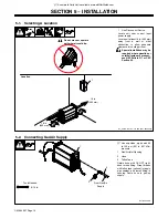
5-1. Selecting A Location
loc_2 3/96 - Ref. ST-151 556 / Ref. 264 254-B
1
Line Disconnect Device
Locate unit near correct input
power supply.
Locate unit at least 18 in. (460 mm)
away from a wall or other
obstruction to allow adequate
clearance for cooling air flow.
!
Special installation may be
required where gasoline or
volatile liquids are present
−
see NEC Article 511 or CEC
Section 20.
Location
1
18 in.
(460 mm)
18 in.
(460 mm)
!
Do not move or operate
unit where it could tip.
5-2. Connecting Gas/Air Supply
Ref. 805 326-A
.
Use only clean, dry air with 90
to 120 psi (621 to 827 kPa)
pressure.
1
Gas/Air Inlet Opening
2
Hose
3
Teflon Tape
Obtain hose with 1/4 NPT right-
hand thread fitting. Wrap threads
with teflon tape (optional) or apply
pipe sealant, and install fitting in
opening. Route hose to gas/air
supply.
Tools Needed:
9/16 in.
3
From Gas/Air
Supply
1
2
Содержание XT40 Torch
Страница 23: ...A complete Parts List is available at www MillerWelds com OM 264 267 Page 19 Notes...
Страница 40: ...OM 264 267 Page 36 SECTION 9 ELECTRICAL DIAGRAM Figure 9 1 Circuit Diagram For Spectrum 625 X TREME...
Страница 41: ...OM 264 267 Page 37 264 143 A...
Страница 42: ...OM 264 267 Page 38 Figure 9 2 Circuit Diagram For Spectrum 625 X TREME CNC...
Страница 43: ...OM 264 267 Page 39 265 480 A...
Страница 48: ...Notes...
Страница 50: ...Notes Work like a Pro Pros weld and cut safely Read the safety rules at the beginning of this manual...


