OM-257 675 Page 36
9-3. Automated Welding Equipment Recommendations
Planning proper layout and routing of welding cables and control cables should be considered when setting up automated equipment.
1.
Whenever possible all cables should be routed out of the path of moving equipment.
2.
Cable installation in a stationary position will decrease the likelihood of wires breaking down in the cable.
3.
Cables that are moving will breakdown over time. This time can be increased by making sure there are no stress points when installing cables,
and deciding how and where to tie cables down.
4.
If at all possible, do not route weld cables and control cables together. Leave as much space as reasonable between the weld cables and any
other control cables. Welding generates electrical noise which is present on the weld cables (see 9-9 for grounding information).
9-4. Process Considerations
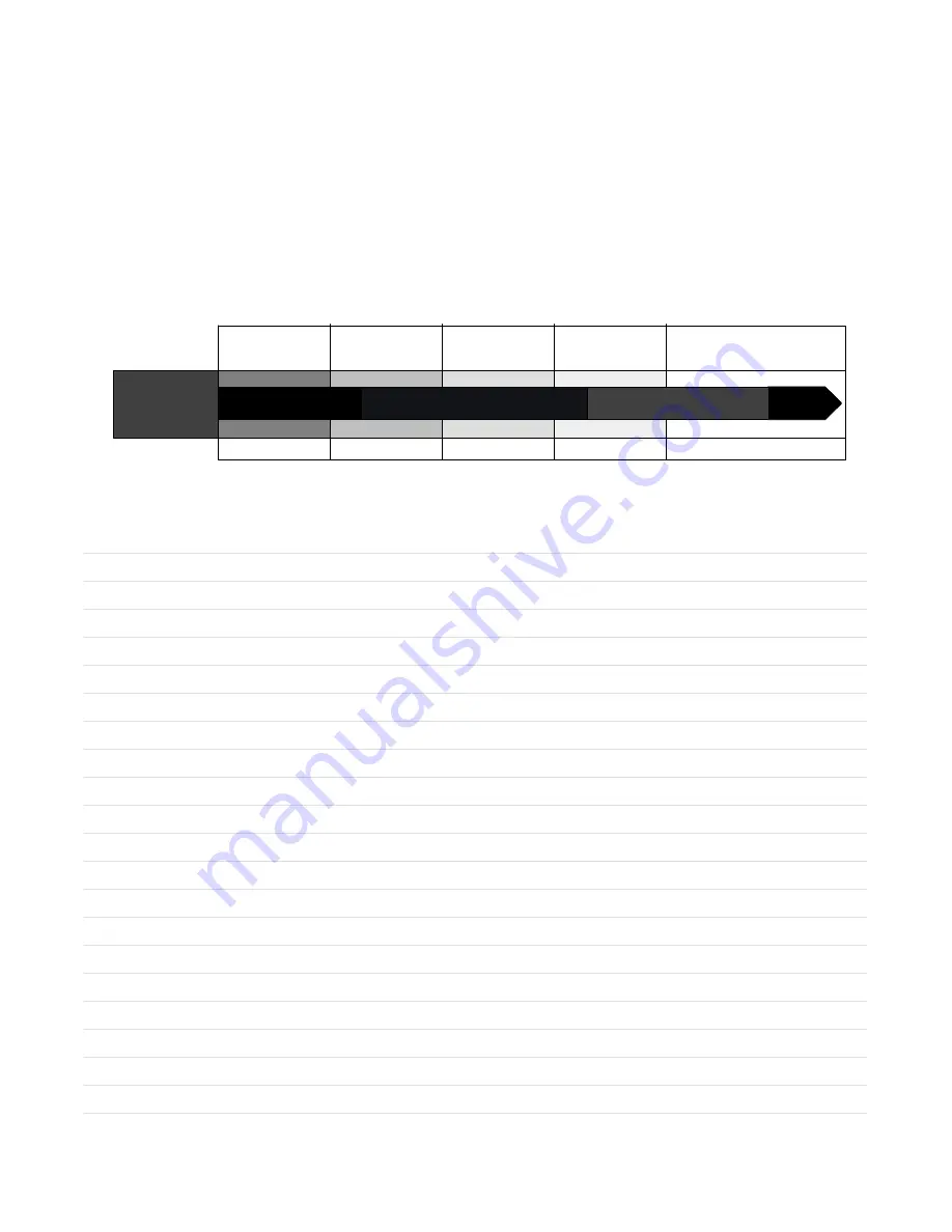
To obtain the most performance from the welding equipment, it is important to use the right transfer mode for the application. There are no hard and fast
rules, but there are general guidelines to follow when making a selection. The transfer modes available depend on the power source being used. The
possible transfer modes are as follows: Short Arc, Spray, Pulsed Spray, Accu-pulse, and RMD (Regulated Metal Deposition).
Weld Puddle
Control
Process
Standard
Spray
Pulsed
Spray
Accu-pulse
t
Standard
Short Circuit
RMD
t
Regulate Metal
Deposition
Flat/Horizontal
All Position Performance
Thin Material/Gap Filling
Note: To achieve optimum performance, 4/0 welding secondary cable is recommended and the supplied work sense lead must be
connected as close to the arc as possible.
Notes
Содержание Auto-Axcess E Digital
Страница 6: ......
Страница 16: ...OM 257 675 Page 10...
Страница 18: ...OM 257 675 Page 12 Notes...
Страница 22: ...OM 257 675 Page 16 Notes...
Страница 26: ...OM 257 675 Page 20 Notes...
Страница 30: ...OM 257 675 Page 24 Notes...
Страница 37: ...General OM 257 675 Page 31 Notes...
Страница 98: ...Safety OM 257 675 Page 92 Notes...
Страница 115: ...Trouble OM 257 675 Page 109 Notes...
Страница 120: ...OM 257 675 Page 114 Figure 15 2 Circuit Diagram For Auto Axcess E 300 Digital Welding Power Source Part 2 Of 2...
Страница 121: ...Circuits OM 257 675 Page 115 257 679 A Part 2 Of 2...
Страница 122: ...OM 257 675 Page 116 Figure 15 3 Circuit Diagram For Auto Axcess E 450 Digital Welding Power Source Part 1 Of 2...
Страница 123: ...Circuits OM 257 675 Page 117 257 678 A Part 1 Of 2...
Страница 124: ...OM 257 675 Page 118 Figure 15 4 Circuit Diagram For Auto Axcess E 450 Digital Welding Power Source Part 2 Of 2...
Страница 125: ...Circuits OM 257 675 Page 119 257 678 A Part 2 Of 2...
Страница 126: ...OM 257 675 Page 120 Figure 15 5 Circuit Diagram For Auto Axcess E 675 Digital Welding Power Source Part 1 Of 2...
Страница 127: ...Circuits OM 257 675 Page 121 257 676 A Part 1 Of 2...
Страница 128: ...OM 257 675 Page 122 Figure 15 6 Circuit Diagram For Auto Axcess E 675 Digital Welding Power Source Part 2 Of 2...
Страница 129: ...Circuits OM 257 675 Page 123 257 676 A Part 2 Of 2...
Страница 130: ...OM 257 675 Page 124 Figure 15 7 Circuit Diagram For Axcess E Digital Module...
Страница 131: ...Circuits OM 257 675 Page 125 257 680 A...
Страница 132: ...OM 257 675 Page 126 Figure 15 8 Circuit Diagram For Motor And Digital I O Interface...
Страница 133: ...Circuits OM 257 675 Page 127 258 246 A...
Страница 143: ...E450 Parts OM 257 675 Page 137 Notes...
Страница 153: ...E675 Parts OM 257 675 Page 147 Notes...


