Miele G 600 Series, Техническая информация
"Серия Miele G 600 предлагает высокое качество и техническую информацию о продукте. Вы можете бесплатно скачать руководство по эксплуатации с нашего сайта. Получите всю необходимую информацию о продукте для его правильного использования. Посетите manualshive.com для загрузки."
Поделиться
Скачать


Отзывы:
Нет отзывов
Похожие инструкции для G 600 Series

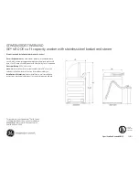
GTWN5550DWW
Бренд: GE Страницы: 2

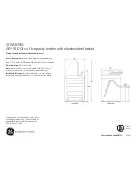
GTWN5250DWW
Бренд: GE Страницы: 2
GTWS8450DWS
Бренд: GE Страницы: 2
GFWH2400L Series
Бренд: GE Страницы: 52

Profile PTWN8055MMS
Бренд: GE Страницы: 101
Profile PTWN6050MWT
Бренд: GE Страницы: 2

Profile PTWN8055MMS
Бренд: GE Страницы: 46
GTWN8250DWS
Бренд: GE Страницы: 2

Profile WPRB9220
Бренд: GE Страницы: 20

Profile ENERGY STAR WPRE6150K
Бренд: GE Страницы: 2
Profile PTWN6050M
Бренд: GE Страницы: 24
GFW148
Бренд: GE Страницы: 24
GTW460
Бренд: GE Страницы: 80
GTWN4250M
Бренд: GE Страницы: 24
GFWN1100L
Бренд: GE Страницы: 52

SPACEMAKER WSKS3040E
Бренд: GE Страницы: 3

3VT913NA - annexe 1
Бренд: BALAY Страницы: 25

3VT913NA - annexe 1
Бренд: BALAY Страницы: 30


