4-22
SECTION 4
SECTION 4
MAINTENANCE
ENTRETIEN
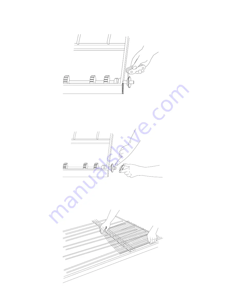
13. Slide the inner roller
chain sprocket onto the
shaft (Figure 4-47). This
sprocket drives the con-
veyor belt. Tighten its
set- screw to extend it
into the hole of the hol-
low shaft. It
should NOT
touch the inner solid
shaft. Check to see that,
only the rear (solid) shaft
moves, when the
sprocket is turned. (If
both shafts move, un-
screw the setscrew until
only the rear (solid) shaft
moves when the inner
roller chain sprocket is
turned.
13. Introduire le pignon
dentraînement intérieur
sur larbre (Figure 4-47).
Ce pignon entraîne le tapis
de convoyeur. Serrer la vis
de pignon dentraînement
jusquà ce quelle pénètre
dans le trou de larbre creux
mais
sans quelle touche
larbre intérieur plein.
Sassurera que seul larbre
arrière tourne lorsque lon
fait tourner le pignon. Si
les deux arbres tournent, la
vis est trop serrée. Il faut
alors la desserrer jusquà
ce que seul larbre arrière
tourne lorsque lon fait
tourner le pignon.
14. Install the small nylon
spacer next to the inner
roller chain sprocket.
Install the sprocket inte-
rior bushing in the outer
roller chain sprocket
before mounting the
sprocket on the end of
the drive shaft (Figure
4-48). Tighten the set-
screw, making sure the
setscrew goes through
the slot in the adaptor
bushing and locks onto
the inner (solid) shaft.
15. Thread the conveyor
belts back onto frame,
making sure the links will
be traveling in the proper
direction.
16. Perform the conveyor
reassembly instructions
in
Monthly Mainte-
nance
.
14. Placer la petite bague
despacement en nylon
contre le pignon
dentraînement de larbre
intérieur. Introduire la
douille dans le pignon
dentraînement de larbre
extérieur avec de monter
ce pignon sur lextrémité
de larbre dentraînement
(Figure 4-48). Serrer la vis
de fixation du pignon en
sassurant quelle passe par
la fente de la douille et
quelle fait pression sur
larbre intérieur (arbre
plein).
15. Remettre les tapis de
convoyeur en place dans le
cadre en veillant à ce que
les chaînons soient
correctement orientés par
rapport au sens de
déplacement.
16. Suivre les instructions de
remontage du convoyeur
figurant au
section sur
lEntretien mensuel
.
Figure 4-47
Figure 4-47
Figure 4-48
Figure 4-48
Figure 4-49
Figure 4-49
Содержание PS570 series
Страница 8: ...NOTES vii...
Страница 17: ...1 9 SECTION 1 SECTION 1 DESCRIPTION DESCRIPTION Figure 1 9 Fingers Figure 1 9 Doigt de chauffage...
Страница 18: ...1 10 SECTION 1 SECTION 1 DESCRIPTION DESCRIPTION NOTES...
Страница 32: ...2 14 SECTION 2 SECTION 2 INSTALLATION INSTALLATION NOTES...
Страница 72: ...5 4 SECTION 5 SECTION 5 TROUBLESHOOTING D PANNAGE NOTES...
Страница 74: ...6 2 SECTION 6 SECTION 6 ELECTRICAL SCHEMATICS SCH MAS LECTRIQUES Gas Oven Wiring Diagram Model PS570 208 240V...
Страница 75: ...6 3 SECTION 6 SECTION 6 ELECTRICAL SCHEMATICS SCH MAS LECTRIQUES Sch ma des Fours Gaz Mod le PS570 208 240V...


