4-21
SECTION 4
SECTION 4
MAINTENANCE
ENTRETIEN
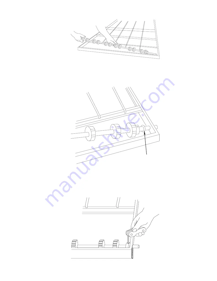
10. Push the end of the con-
veyor drive shaft (from
which the roller chain
sprockets were re-
moved) through the
conveyor frame. Then,
lift the opposite end of
the shaft while pulling it
back out of the frame,
as shown in Figure 4-
44. Perform the clean-
ing and lubricating pro-
cedures of Steps 5-6.
10. Pousser lextrémité de
larbre dentraînement du
convoyeur doù les
pignons de la chaîne
dentraînement ont été
démontés vers lintérieur
du cadre. Soulever
lextrémité opposée de
larbre en le tirant pour le
sortir du cadre comme
illustré à la Figure 4-44.
Nettoyer larbre comme
indiqué aux étapes 5 et 6
ci-dessus.
11. Reassemble the con-
veyor drive shaft. Then
reinstall it into the right
side of the conveyor
frame, making sure that
the large nylon spacer
(arrow, Figure 4-45) is
in place.
12. Slide the conveyor drive
shaft into the bushing
on its left end, then into
the hole of the conveyor
frame. Hold the drive
shaft in place and slide
the split locking collar
toward the right end.
Tighten the setscrew of
the split locking collar
(Figure 4-46).
11. Remonter larbre
dentraînement du
convoyeur. Lengager
dans le côté droite du cadre
de convoyeur en sassurant
que la bague despacement
en nylon (Figure 4-45) est
bien en place.
12. Introduire larbre
dentraînement de
convoyeur dans la douille
placée à son extrémité
gauche, puis dans le trou
du cadre de convoyeur.
Maintenir larbre en place,
faire coulisser le collier
fendu de fixation vers la
droite et serrer la vis du
collier (Figure 4-46).
Figure 4-44
Figure 4-44
Figure 4-45
Figure 4-45
Figure 4-46
Figure 4-46
Содержание PS570 series
Страница 8: ...NOTES vii...
Страница 17: ...1 9 SECTION 1 SECTION 1 DESCRIPTION DESCRIPTION Figure 1 9 Fingers Figure 1 9 Doigt de chauffage...
Страница 18: ...1 10 SECTION 1 SECTION 1 DESCRIPTION DESCRIPTION NOTES...
Страница 32: ...2 14 SECTION 2 SECTION 2 INSTALLATION INSTALLATION NOTES...
Страница 72: ...5 4 SECTION 5 SECTION 5 TROUBLESHOOTING D PANNAGE NOTES...
Страница 74: ...6 2 SECTION 6 SECTION 6 ELECTRICAL SCHEMATICS SCH MAS LECTRIQUES Gas Oven Wiring Diagram Model PS570 208 240V...
Страница 75: ...6 3 SECTION 6 SECTION 6 ELECTRICAL SCHEMATICS SCH MAS LECTRIQUES Sch ma des Fours Gaz Mod le PS570 208 240V...


