4-3
SECTION 4
SECTION 4
MAINTENANCE
ENTRETIEN
C. Conveyor Belts
While the conveyor is operating, stand at the unloading end
of the conveyor. Using a brush, simply brush off any excess
crumbs into the crumb pan below.
D. Crumb Pans
Remove and clean the crumb pans at both ends of the oven.
Depending on the available space around the oven, the
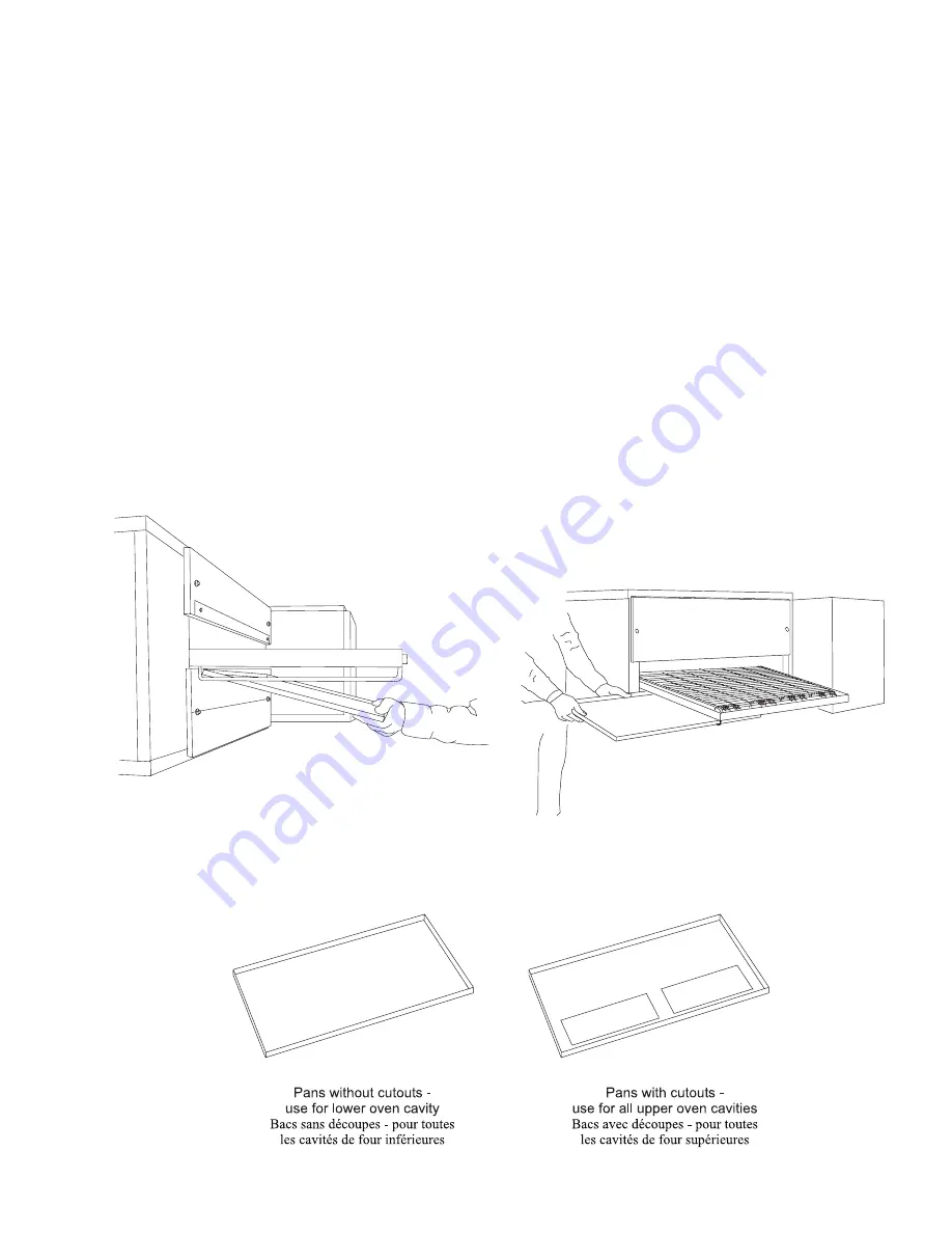
crumb pans can be removed in either of the following ways:
Lift the end of the pan slightly, then push the pan towards
the oven. The end of the pan can then be lowered, and
the pan can be removed from the end of the oven. See
Figure 4-3.
Slide the pan out from underneath the conveyor, towards
the front of the oven. See Figure 4-3. This method can
only be used on the right side of the oven, because the
conveyor drive motor cover blocks the left pan from sliding
out.
When you replace the crumb trays, be sure to note whether
cutouts are present in the bottom of the pan. The crumb
pans without cutouts should be reinstalled on the lower oven
cavity. The pans with cutouts should be reinstalled on the
upper oven cavities. See Figure 4-4.
C. Tapis du convoyeur
Nettoyer le tapis du convoyeur avec une brosse dure. Se placer à
lextrémité de déchargement du convoyeur et brosser les miettes
pour les faire tomber dans le tiroir à miettes.
D.
Tiroirs à miettes
Retirer et nettoyer les bacs à miettes des deux côtés du four. Suivant
lespace disponible autour du four, les bacs à miettes peuvent être
retirés de lune ou lautre des façons suivantes :
Soulever légèrement lextrémité du bac puis pousser le bac en
direction du four. Lextrémité du bac peut être abaissée et le bac
retiré du four. Voir la figure 4-3.
Sortir le bac du dessous du convoyeur, vers lavant du four. Voir
la figure 4-3. Cette méthode ne peut être utilisée que du côté droit
du four car le moteur dentraînement du convoyeur bloque le
passage du bac de gauche.
Lors de la remise en place des bacs à miettes, regarder si leur font
comporte des découpes. Le bacs à miettes sans découpes doivent
être installés dans la cavité inférieure du four. Les bacs pourvus de
découpes doivent être installés dans la cavité supérieure.
Figure 4-3 - Removing the Crumb Trays
Figure 4-3 - Retrait des bacs à miettes
...from the front of the oven
(right side only)
de lavant du four
(côté droit seulement)
Figure 4-4 - Crumb Tray Reinstallation
Figure 4-4 -
Remise en place des bacs à miettes
...from the end of the oven
de larrière du four
Содержание PS570 series
Страница 8: ...NOTES vii...
Страница 17: ...1 9 SECTION 1 SECTION 1 DESCRIPTION DESCRIPTION Figure 1 9 Fingers Figure 1 9 Doigt de chauffage...
Страница 18: ...1 10 SECTION 1 SECTION 1 DESCRIPTION DESCRIPTION NOTES...
Страница 32: ...2 14 SECTION 2 SECTION 2 INSTALLATION INSTALLATION NOTES...
Страница 72: ...5 4 SECTION 5 SECTION 5 TROUBLESHOOTING D PANNAGE NOTES...
Страница 74: ...6 2 SECTION 6 SECTION 6 ELECTRICAL SCHEMATICS SCH MAS LECTRIQUES Gas Oven Wiring Diagram Model PS570 208 240V...
Страница 75: ...6 3 SECTION 6 SECTION 6 ELECTRICAL SCHEMATICS SCH MAS LECTRIQUES Sch ma des Fours Gaz Mod le PS570 208 240V...


