


Functional safety technology
Page 56
Product Manual
“Servo drive DIS-2 310/2 FB FS STO“
Version 4.0
1
st
disconnection path:
Via STO1 (X40.1), the PWM signals from the DSP are inhibited by setting the
enabling pin of the 8-pin line driver to "high". As a result, the output stage drivers will no longer be
actuated by pulse patterns.
2
nd
disconnection path:
The input voltage for the DCDC converter is disconnected via STO2 (X40.5).
This also disconnects the +15 V-TR supply voltage for the power module and the 5 V-TR supply
voltage for the output stage drivers.
There are so-called feedback paths for both channels:
Feedback for the STO1 disconnection path is realised via the eighth channel of the PWM line driver.
When the signals are blocked, the channel will assume a high resistance at the output so that the
"PMW signal feedback" signal assumes the logic state 1.
The feedback for disconnection path 2 is realised in an indirect manner via the "power unit temperature
(T-LT)" signal. The temperature is transferred digitally (square-wave signal) to the small-voltage end
(DGND potential) via a channel of the output stage drivers. In the permissible temperature range, the
configuration of the transfer circuit ensures that the signal is always a square-wave signal during the
operation. When the driver supply is disconnected via STO2, the "driver supply feedback" signal
assumes the logic state 1.
For self-diagnosis, the enable signals STO1 and STO2 and the associated feedback signals will be
checked for plausibility in the DSP.
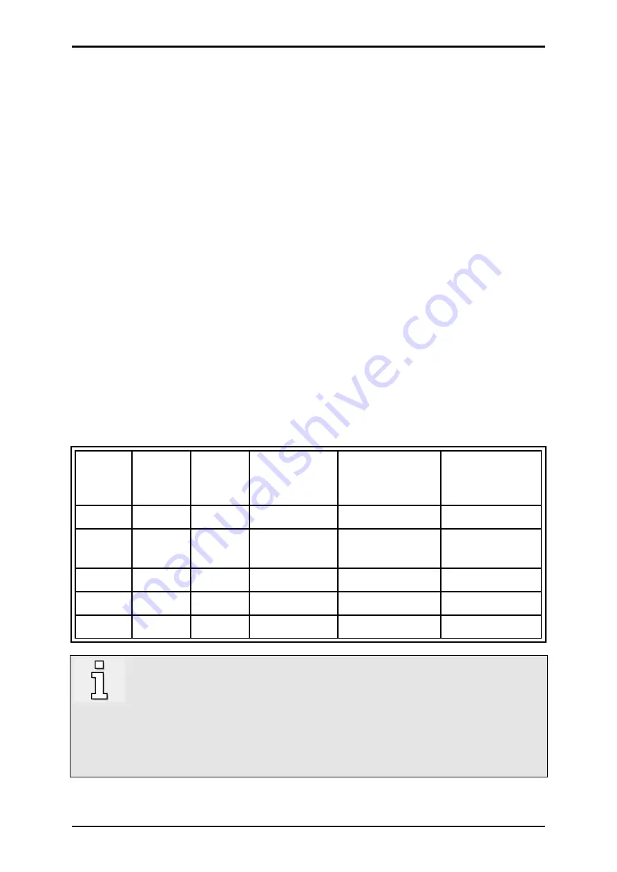
The plausibility check or the test of the safety function will be performed in accordance with the
following truth table:
Table 26:
STO signal plausibility table
24 V
STO1
STO2
PWM signal
feedback
(STO1)
Driver supply
feedback
(STO2)
Normally open
contact
REL 1/2
OFF
X
X
X
X
open
ON
0 V
0 V
1
1
closed
(safe state STO)
ON
24 V
0 V
0
1
open
ON
0 V
24 V
1
0
open
ON
24 V
24 V
0
0
open
Note
Floating feedback contact: If an external diagnosis is required, the semiconductor relay
transfers the "safe" or "unsafe" state to a superordinate control system. The PLC must
perform a plausibility check in accordance with
achieved) at regular, suitable intervals (see the note in
section 6.1
). If an error occurs
during the plausibility check, the further operation of the system must be prevented by the
control system, e.g. by blocking the enable signal or by switching the mains contactor off.


