


DN
[mm]
Pressure
class PN
Flanges according to DIN EN 1092-1
Hexagon screws and nuts
Min. operating
temp. of the
screws and
nuts
Number of
screws
Screw
material
Nut
material
Length of the
threaded rods
PN16 ANSI B16.5
Class150
25*
16
-40°C
4 x M12
25CrMo4
50
16
-40°C
4 x M16
25CrMo4
25CrMo4
165
170
80
16
-40°C
8 x M16
25CrMo4
25CrMo4
210
225
100
16
-40°C
8 x M16
25CrMo4
25CrMo4
240
255
150
16
-40°C
8 x M20
25CrMo4
25CrMo4
285
312
* Flange with threaded holes
7.4
Implementation
Installation of the MQMe Quantometer
1.
Clean the flange surfaces (e.g. with petroleum).
2.
The meter should preferably be installed horizontally with the meter index at the top.
3.
The gas must flow in the direction of the arrow indicated on the meter.
4.
During the installation, check that the gaskets are fitted concentrically so that no
sealing elements protrude into the pipeline.
5.
In addition to the length of the meter itself, it is necessary to leave enough room for the
two gaskets between the inlet and outlet flanges for the installation.
6.
The meter must be installed without any tension. For this purpose, ensure that the
meter axis is properly aligned with the pipeline axis.
7.
Carry out a proper leak test of the flange connections.
8.
If necessary, turn the general direction of the meter display by 180°, see “Changing the
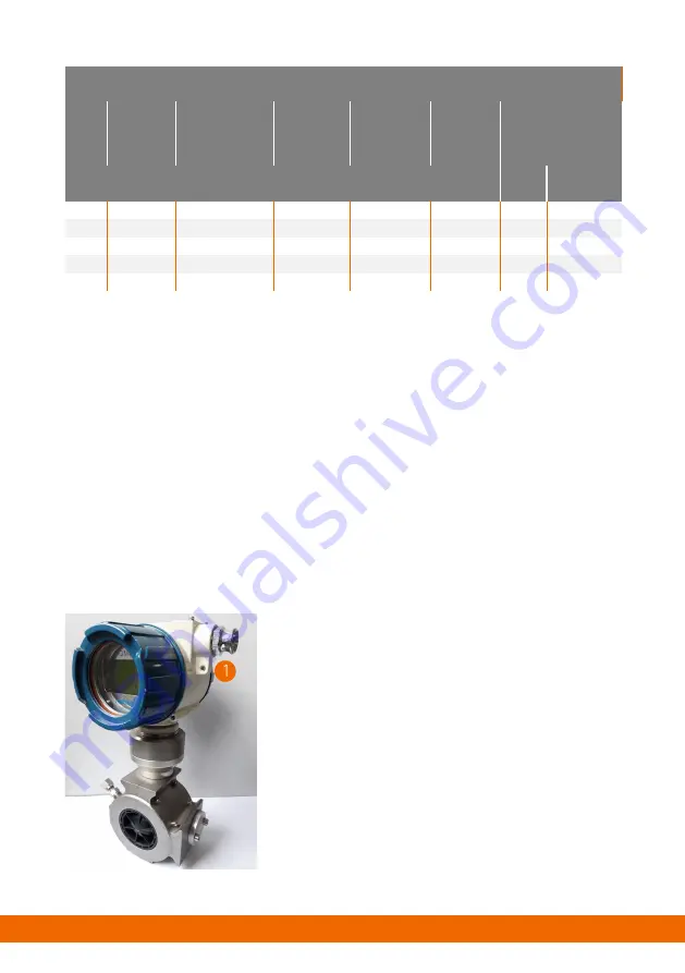
1
Screw connection on the meter index head
9.
Connect the equipotential bonding with a
minimum cross-section of 4 mm² to the
screw connection provided for this
purpose on the meter index head (1).
Fig. 4 Connection for the equipotential bonding
12